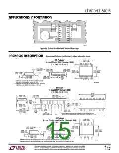
LT1510/LT1510-5
U
W U U
APPLICATIONS INFORMATION
Example: VIN = 15V, VBAT = 8.4V, IBAT = 1.2A;
PBIAS = 3.5mA 15 +1.5mA 8.4
The average IVX required is:
P
0.045W
3.3V
DRIVER
(
)( )
(
)
=
= 14mA
VX
8.4 2
(
)
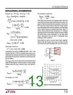
Total board area becomes an important factor when the
areaoftheboarddropsbelowabout20squareinches. The
graph in Figure 9 shows thermal resistance vs board area
for 2-layer and 4-layer boards. Note that 4-layer boards
havesignificantlylowerthermalresistance, butbothtypes
show a rapid increase for reduced board areas. Figure 10
shows actual measured lead temperature for chargers
operating at full current. Battery voltage and input voltage
will affect device power dissipation, so the data sheet
power calculations must be used to extrapolate these
readings to other situations.
+
7.5mA + 0.012 1.2 = 0.17W
(
)(
)
]
[
15
1.2 8.4 2 1+
8.4
(
)(
)
30
P
=
= 0.13W
DRIVER
55 15
( )
2
1.2 0.35 8.4
(
) (
)(
)
P
=
+
SW
15
−9
10 •10
15 1.2 200kHz
( )( )(
)
= 0.28 + 0.04 = 0.32W
Vias should be used to connect board layers together.
Planes under the charger area can be cut away from the
rest of the board and connected with vias to form both a
2
)
P
= 0.18 1.2 = 0.26W
(
)(
SENSE
Total power in the IC is:
SW
0.17 + 0.13 + 0.32+ 0.26 = 0.88W
LT1510
C1
D2
BOOST
L1
Temperature rise will be (0.88W)(50°C/W) = 44°C. This
assumes that the LT1510 is properly heat sunk by con-
necting the four fused ground pins to the expanded traces
and that the PC board has a backside or internal plane for
heat spreading.
SENSE
V
X
1510 F07
+
I
VX
10µF
Figure 8
The PDRIVER term can be reduced by connecting the boost
diode D2 (see Figures 2 and 6 circuits) to a lower system
voltage (lower than VBAT) instead of VBAT (see Figure 8).
60
55
50
45
40
35
30
25
Then,
2-LAYER BOARD
4-LAYER BOARD
VX
30
I
V
V
1+
(
BAT)( BAT)( )
X
PDRIVER
=
55 V
(
)
IN
S16, MEASURED FROM AIR AMBIENT
TO DIE USING COPPER LANDS AS
SHOWN ON DATA SHEET
For example, VX = 3.3V,
20
BOARD AREA (IN2)
25
30
35
0
5
10
15
3.3V
30
1.2A 8.4V 3.3V 1+
(
)(
)(
)
)
1510 F08
PDRIVER
=
= 0.045W
Figure 9. LT1510 Thermal Resistance
55 15V
(
13

 Linear [ Linear ]