LT1510/LT1510-5
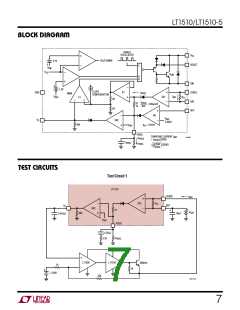
TEST CIRCUITS
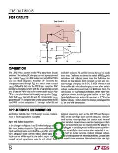
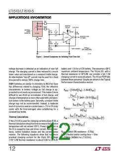
Test Circuit 2
LT1510
OVP
+
VA
–
V
REF
PROG
10k
10k
I
PROG
–
LT1013
+
+
0.47µF
R
PROG
2.465V
1510 TC02
U
OPERATIO
The LT1510 is a current mode PWM step-down (buck)
switcher. The battery DC charging current is programmed
by a resistor RPROG (or a DAC output current) at the PROG
pin (see Block Diagram). Amplifier CA1 converts the
charging current through RS1 to a much lower current
IPROG (500µA/A) fed into the PROG pin. Amplifier CA2
compares the output of CA1 with the programmed current
and drives the PWM loop to force them to be equal. High
level shift resistors R2 and R3, forming the current mode
inner loop. The Boost pin drives the switch NPN QSW into
saturation and reduces power loss. For batteries like
lithium-ion that require both constant-current and con-
stant-voltage charging, the 0.5%, 2.465V reference and
the amplifier VA reduce the charging current when battery
voltage reaches the preset level. For NiMH and NiCd, VA
can be used for overvoltage protection. When input volt-
age is not present, the charger goes into low current (3µA
typically) sleep mode as input drops down to 0.7V below
battery voltage. To shut down the charger, simply pull the
VC pin low with a transistor.
DC accuracy is achieved with averaging capacitor CPROG
.
Note that IPROG has both AC and DC components. IPROG
goes through R1 and generates a ramp signal that is fed to
the PWM control comparator C1 through buffer B1 and
U
W U U
APPLICATIONS INFORMATION
tantalum capacitors such as the AVX TPS and Sprague
593D series have high ripple current rating in a relatively
small surface mount package, but caution must be used
when tantalum capacitors are used for input bypass. High
input surge currents can be created when the adapter is
hot-plugged to the charger and solid tantalum capacitors
have a known failure mechanism when subjected to very
high turn-on surge currents. Highest possible voltage
rating on the capacitor will minimize problems. Consult with
the manufacturer before use. Alternatives include new high
Application Note 68, the LT1510 design manual, contains
more in depth appications examples.
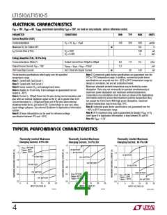
Input and Output Capacitors
In the chargers in Figures 1 and 2 on the first page of this
datasheet, theinputcapacitorCIN isassumedtoabsorball
input switching ripple current in the converter, so it must
have adequate ripple current rating. Worst-case RMS
ripple current will be equal to one half of output charging
current. Actual capacitance value is not critical. Solid
8

 Linear [ Linear ]