LT1510/LT1510-5
U
W U U
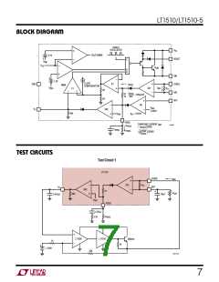
APPLICATIONS INFORMATION
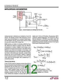
of the battery, canceling part or all of the 200µA. Note that
if net current is into the battery and the battery is removed,
the charger output voltage will float high, to near input
voltage. This could be a problem when reinserting the
battery, if the resulting output capacitor/battery surge
current is high enough to damage either the battery or the
capacitor.
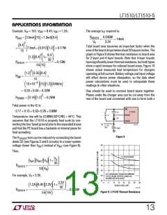
period, after which the LT1510 can be shut down by
pulling the VC pin low with an open collector or drain.
Some external means must be used to detect the need for
additional charging if needed, or the charger may be
turned on periodically to complete a short float-voltage
cycle.
Current trip level is determined by the battery voltage, R1
through R3, and the internal LT1510 sense resistor
(≈ 0.18Ω pin-to-pin). D2 generates hysteresis in the trip
level to avoid multiple comparator transitions.
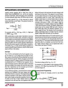
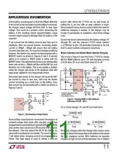
If net current into the battery must be less than zero in
shutdown, there are several options. Increasing divider
current to 300µA - 400µA will ensure that net battery
current is less than zero. For long term storage conditions
however, the divider may need to be disconnected with a
MOSFET switch as shown in Figures 2 and 5. A second
option is to connect a 1N914 diode in series with the
MOSFET drain. This will limit how far the VC pin will be pulled
down, and current (≈ 700µA) will flow into the BAT pin, and
therefore out of the battery. This is not usually a problem
unless the charger will remain in the shutdown state with
input power applied for very long periods of time.
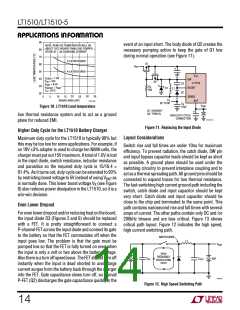
Nickel-Cadmium and Nickel-Metal-Hydride Charging
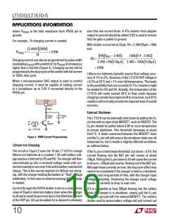
The circuit in Figure 6 uses the 8-pin LT1510 to charge
NiCd or NiMH batteries up to 12V with charging currents
of 0.5A when Q1 is on and 50mA when Q1 is off.
D3
1N5819
C1
0.22µF
D1
1N5819
SW
V
CC
+
C
*
IN
WALL
ADAPTER
10µF
Removing input power to the charger will cause the BAT
pin current to drop to near zero, with only the divider
current remaining as a small drain on the battery. Even
that current can be eliminated with a switch as shown in
Figures 2 and 5.
BOOST PROG
LT1510
1µF
L1**
33µH
R1
300Ω
100k
D2
1N914
R2
11k
0.1µF
GND
V
C
1k
Q1
VN2222
I
BAT
SENSE
BAT
ON: I
= 0.5A
BAT
BAT
+
+
OFF: I
= 0.05A
C
2V TO
20V
OUT
*
TOKIN OR MARCON CERAMIC
SURFACE MOUNT
** COILTRONICS CTX33-2
22µF
V
BAT
+
TANT
1510 F05.5
R3
4.2V
4.2V
12k
–
+
R5
220k
Figure 6. Charging NiMH or NiCd Batteries
(Efficiency at 0.5A ≈ 90%)
Q3
VN2222
LT1510
OVP
–
V
IN
R4
4.99k
0.25%
For a 2-level charger, R1 and R2 are found from:
1510 F05
2000 2.465
(
)(
)
Figure 5. Disconnecting Voltage Divider
IBAT
=
(
RPROG
Some battery manufacturers recommend termination of
constant-voltage float mode after charging current has
droppedbelowaspecifiedlevel(typically50mAto100mA)
and a further time-out period of 30 minutes to 90 minutes
has elapsed. This may extend the life of the battery, so
check with manufacturers for details. The circuit in Figure
7 will detect when charging current has dropped below
75mA. This logic signal is used to initiate a time-out
2.465 2000
2.465 2000
)(
)
(
)(
)
R1=
R2 =
ILOW
IHI −ILOW
All battery chargers with fast-charge rates require some
meanstodetectfullchargestateinthebatterytoterminate
the high charging current. NiCd batteries are typically
charged at high current until temperature rise or battery
11

 Linear [ Linear ]