LT1510/LT1510-5
ELECTRICAL CHARACTERISTICS
VCC = 16V, VBAT = 8V, VMAX (maximum operating VCC) = 28V, no load on any outputs, unless otherwise noted.
PARAMETER
CONDITIONS
MIN
TYP
MAX
UNITS
Current Amplifier (CA2)
Transconductance
V = 1V, I = ±1µA
150
250
550
0.6
µmho
C
VC
Maximum V for Switch OFF
●
V
C
I
Current (Out of Pin)
V ≥ 0.6V
C
100
3
µA
mA
VC
C
V < 0.45V
Voltage Amplifier (VA), 16-Pin Only
Transconductance (Note 2)
Output Current from 100µA to 500µA
0.5
1.3
1.2
50
2.5
mho
mA
nA
Output Source Current, V = 10V
V
PROG
= V
= V
+ 10mV
CC
OVP
REF
OVP Input Bias Current
At 0.75mA VA Output Current
●
150
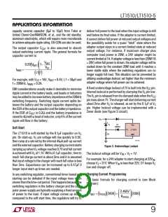
The
●
denotes specifications which apply over the specified
Note 7: Commercial grade device specifications are guaranteed over the
0°C to 70°C temperature range. In addition, commercial grade device
specifications are assured over the –40°C to 85°C temperature range by
design or correlation, but are not production tested.
temperature range.
Note 1: Tested with Test Circuit 1.
Note 2: Tested with Test Circuit 2.
Maximum allowable ambient temperature may be limited by power
dissipation. Parts may not necessarily be operated simultaneously at
maximum power dissipation and maximum ambient temperature.
Temperature rise calculations must be done as shown in the Applications
Information section to ensure that maximum junction temperature does
not exceed the 125°C limit. With high power dissipation, maximum
ambient temperature may be less than 70°C.
Note 3: Sense resistor R and package bond wires.
Note 4: Applies to 16-pin only. 8-pin packages are guaranteed but not
tested at –40°C.
S1
Note 5: Current (≈ 700µA) flows into the pins during normal operation and
also when an external shutdown signal on the V pin is greater than 0.3V.
C
Current decreases to ≈ 200µA and flows out of the pins when external
shutdown holds the V pin below 0.3V. Current drops to near zero when
C
Note 8: Industrial grade device specifications are guaranteed over the
–40°C to 85°C temperature range.
input voltage collapses. See external Shutdown in Applications Information
section.
Note 9: 91% maximum duty cycle is guaranteed by design if V
or V
BAT
X
Note 6: A linear interpolation can be used for reference voltage
specification between 0°C and –40°C.
(see Figure 8 in Application Information) is kept between 3V and 5V.
Note 10: V
= 4.2V.
BAT
W
U
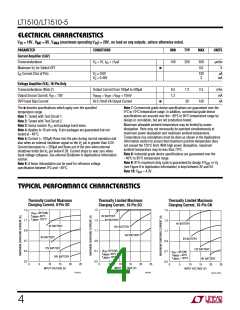
TYPICAL PERFORMANCE CHARACTERISTICS
Thermally Limited Maximum
Charging Current, 8-Pin SO
Thermally Limited Maximum
Charging Current, 16-Pin SO
Thermally Limited Maximum
Charging Current, 16-Pin GN
1.5
1.3
1.1
0.9
0.7
0.5
1.3
1.1
0.9
0.7
0.5
0.3
1.5
1.3
1.1
0.9
0.7
0.5
(θ =125°C/W)
JA
AMAX
JMAX
T
T
=60°C
=125°C
4V BATTERY
8V BATTERY
4V BATTERY
4V BATTERY
12V BATTERY
16V BATTERY
8V BATTERY
8V BATTERY
12V BATTERY
12V BATTERY
16V BATTERY
(θ =50°C/W)
JA
AMAX
JMAX
θ
T
T
= 80°C/W
AMAX
JMAX
JA
T
T
=60°C
=125°C
= 60°C
= 125°C
16V BATTERY
15
20
INPUT VOLTAGE (V)
0
5
10
15
20
25
0
5
10
15
20
25
0
5
10
25
INPUT VOLTAGE (V)
INPUT VOLTAGE (V)
1510 G12
1510 G13
LT1510 • TPC14
4

 Linear [ Linear ]