LT1108
PPLICATI
O U
W
U
A
S I FOR ATIO
where VD is the diode drop (0.5V for a 1N5818 Schottky).
Energy required by the inductor per cycle must be equal or
greater than
INDUCTOR SELECTION
General
A DC/DC converter operates by storing energy as mag-
netic flux in an inductor core, and then switching this
energy into the load. Since it is flux, not charge, that is
stored, the output voltage can be higher, lower, or oppo-
site in polarity to the input voltage by choosing an appro-
priate switching topology.
P /
(02)
f
L
OSC
in order for the converter to regulate the output.
When the switch is closed, current in the inductor builds
according to
–R't
L
V
R'
To operate as an efficient energy transfer element, the
inductor must fulfill three requirements. First, the induc-
tancemustbelowenoughfortheinductortostoreadequate
energy under the worst case condition of minimum input
voltage and switch-ON time. The inductance must also be
high enough so maximum current ratings of the LT1108
and inductor are not exceeded at the other worst case
condition of maximum input voltage and ON-time.
IN
I (t) =
1–e
(03)
L
where R' is the sum of the switch equivalent resistance
(0.8Ω typical at 25°C) and the inductor DC resistance.
When the drop across the switch is small compared to VIN,
the simple lossless equation
V
L
IN
Additionally, the inductor core must be able to store the
required flux; i.e., it must not saturate. At power levels
generally encountered with LT1108 based designs, small
surface mount ferrite core units with saturation current
ratings in the 300mA to 1A range and DCR less than 0.4Ω
(depending on application) are adequate.
I
t =
( )
t
(04)
L
can be used. These equations assume that at t = 0,
inductorcurrentiszero.Thissituationiscalled“discontinu-
ous mode operation” in switching regulator parlance.
Setting “t” to the switch-ON time from the LT1108 specifi-
cationtable(typically36µs)willyieldIPEAK foraspecific“L”
and VIN. Once IPEAK is known, energy in the inductor at the
end of the switch-ON time can be calculated as
Lastly, the inductor must have sufficiently low DC resis-
tancesoexcessivepowerisnotlostasheatinthewindings.
An additional consideration is Electro-Magnetic Interfer-
ence (EMI). Toroid and pot core type inductors are recom-
mended in applications where EMI must be kept to a
minimum; for example, where there are sensitive analog
circuitry or transducers nearby. Rod core types are a less
expensive choice where EMI is not a problem. Minimum
and maximum input voltage, output voltage and output
current must be established before an inductor can be
selected.
1
2
2
E = LI
(05)
L
PEAK
EL must be greater than PL/fOSC for the converter to deliver
therequiredpower. ForbestefficiencyIPEAK shouldbekept
to 1A or less. Higher switch currents will cause excessive
drop across the switch resulting in reduced efficiency. In
general, switch current should be held to as low a value as
possible in order to keep switch, diode and inductor losses
at a minimum.
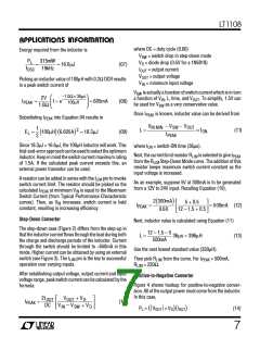
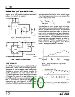
Step-Up Converter
Inastep-up,orboostconverter(Figure1),powergenerated
by the inductor makes up the difference between input and
output. Power required from the inductor is determined by
As an example, suppose 12V at 30mA is to be generated
from a 2V to 3V input. Recalling equation (01),
P = 12V + 0.5V – 2V 30mA = 315mW
(06)
L
P = V
+ V – V
I
) (
OUT
(01)
(
)
MIN
L
OUT
D
IN
6

 Linear [ Linear ]