LT1108
PPLICATI
O U
W
U
A
S I FOR ATIO
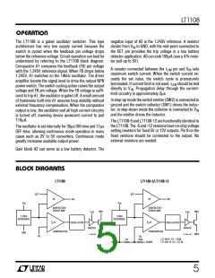
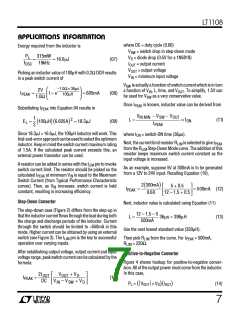
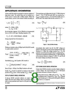
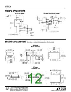
In this mode the switch is arranged in common collector or The usual step-up configuration for the LT1108 is shown in
step-down mode. The switch drop can be modeled as a Figure 1. The LT1108 first pulls SW1 low causing VIN –
0.75V source in series with a 0.65Ω resistor. When the VCESAT to appear across L1. A current then builds up in L1.
switch closes, current in the inductor builds according to
At the end of the switch-ON time the current in L1 is
V
–R't
L
IN
V
R'
L
I
=
t
*
(20)
I
t =
( )
1– e
(15)
PEAK
ON
L
L
D1
L1
where: R' = 0.65Ω + DCRL
V
V
IN
OUT
VL = VIN – 0.75V
R3
R2
R1
As an example, suppose –5V at 100mA is to be generated
from a 4.5V to 5.5V input. Recalling Equation (14),
I
V
LIM
IN
SW1
+
C1
LT1108
FB
PL = ( –5V + 0.5V)(100mA) = 550mW.
Energy required from the inductor is
(16)
GND
SW2
LT1108 • F01
P
550mW
19kHz
L
=
= 28.9µJ
(17)
f
Figure 1. Step-Up Mode Hookup
OSC
Picking an inductor value of 220µH with 0.3Ω DCR results
Immediately after switch turn-off, the SW1 voltage pin
starts to rise because current cannot instantaneously stop
flowing in L1. When the voltage reaches VOUT + VD, the
in a peak switch current of
–0.95Ω × 36µs
220µH
4.5V – 0.75V
(18)
(
(
)
1– e
)
inductorcurrentflowsthroughD1intoC1,increasingVOUT
.
I
=
PEAK
ThisactionisrepeatedasneededbytheLT1108tokeepVFB
at the internal reference voltage of 1.245V. R1 and R2 set
the output voltage according to the formula
0.65Ω + 0.3Ω
= 568mA
Substituting IPEAK into Equation (04) results in
R2
R1
V
= 1+
1.245V
(21)
(
)
OUT
1
2
E = 220µH 0.568A = 35.5µJ
) (
(19)
(
)
L
2
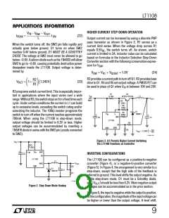
STEP-DOWN (BUCK MODE) OPERATION
Since 35.5µJ > 28.9µJ, the 220µH inductor will work.
A step-down DC/DC converter converts a higher voltage to
a lower voltage. The usual hookup for an LT1108 based
step-down converter is shown in Figure 2.
Finally, RLIM should be selected by looking at the Switch
Current vs RLIM curve. In this example, RLIM = 150Ω.
When the switch turns on, SW2 pulls up to VIN – VSW. This
putsavoltageacrossL1equaltoVIN –VSW –VOUT, causing
acurrenttobuildupinL1. Attheendoftheswitch-ONtime,
the current in L1 is equal to
STEP-UP (BOOST MODE) OPERATION
A step-up DC/DC converter delivers an output voltage
higher than the input voltage. Step-up converters are not
short-circuit protected since there is a DC path from input
to output.
*Expression 20 neglects the effect of switch and coil resistance. This is taken into account in the
"Inductor Selection" section.
8

 Linear [ Linear ]