LT1108
TA = 25°C, VIN = 3V, unless otherwise noted.
ELECTRICAL CHARACTERISTICS
SYMBOL
PARAMETER
CONDITIONS
= 12V, I = 650mA
MIN
TYP
MAX
UNITS
V
SAT
SW Voltage, Step-Down Mode
V
1.1
1.5
1.7
V
V
SAT
IN
SW
●
●
A
V
Gain Block Gain
R = 100k (Note 3)
L
400
1000
400
–0.3
1
V/V
mA
Current Limit
220Ω from I to V
LIM IN
Current Limit Temperature Coefficient
Switch OFF Leakage Current
Maximum Excursion Below GND
●
%/°C
µA
Measured at SW1 Pin
≤ 10µA, Switch OFF
10
V
SW2
I
–400
–350
mV
SW1
The
●
denotes specifications which apply over the full operating
Note 2: The output voltage waveform will exhibit a sawtooth shape due to
the comparator hysteresis. The output voltage on the fixed output versions
will always be within the specified range.
temperature range.
Note 1: This specification guarantees that both the high and low trip points
of the comparator fall within the 1.2V to 1.3V range.
Note 3: 100k resistor connected between a 5V source and the A0 pin.
U W
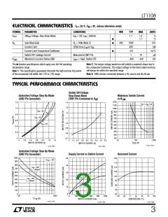
TYPICAL PERFOR A CE CHARACTERISTICS
Switch ON Voltage
Saturation Voltage Step-Up Mode
(SW2 Pin Grounded)
Maximum Switch Current
vs RLIM
Step-Down Mode
(SW1 Pin Connected to VIN)
1200
1100
1000
900
800
700
600
500
400
300
200
100
1.2
1.0
0.8
0.6
0.4
0.2
0
1.4
1.3
2V ≤ V ≤ 5V
IN
V
= 3V
IN
1.2
V
IN
= 2V
1.1
1.0
0.9
0.8
V
IN
= 5V
0.7
10
100
(Ω)
1000
0
0.4
0.6
0.8
1.0
1.2
0.2
0.1 0.2 0.3 0.4
SWITCH CURRENT (A)
0.7 0.8
0
0.5 0.6
R
SWITCH CURRENT (A)
LIM
LT1108 • TPC03
LT1108 • TPC01
LT1108 • TPC02
Saturation Voltage Step-Up Mode
(SW2 Pin Grounded)
Supply Current vs Switch Current
Quiescent Current
1000
900
800
700
600
500
400
300
200
100
0
50
40
30
20
10
0
120
115
110
105
V
= 5V
OUT
V
= 24V
IN
L = 500µH
100
95
V
= 5V
IN
V
= 12V
IN
L = 250µH
90
85
80
V
= 2V
IN
100
1000
0
200
400
600
800
1000
–50
–25
0
50
75
100
25
R
LIM
(Ω)
SWITCH CURRENT (mA)
TEMPERATURE (°C)
LT1108 • TPC04
LTC1108 • TPC05
LT1108 • TPC06
3

 Linear [ Linear ]