LTC2057/LTC2057HV
applicaTions inForMaTion
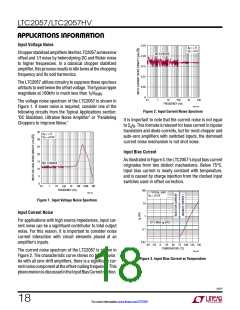
The DC average of injection current is the specified input
bias current, but this current has a frequency component
at the chopping frequency as well. When these small
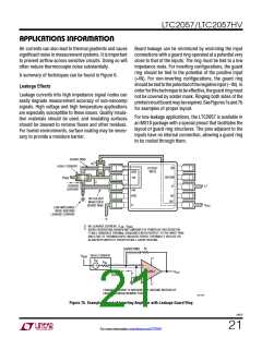
canbemitigatedbymatchingthesourceimpedancesseen
by the two inputs.
Thermocouple Effects
current pulses, typically about 0.7nA
, interact with
RMS
source impedances or gain setting resistors, the resulting
voltage spikes are amplified by the closed loop gain. For
high impedances, this may cause the 100kHz chopping
frequency to be visible in the output spectrum, which is
a phenomenon known as clock feed-through.
In order to achieve accuracy on the microvolt level, ther-
mocouple effects must be considered. Any connection
of dissimilar metals forms a thermoelectric junction and
generates a small temperature-dependent voltage. Also
known as the Seebeck Effect, these thermal EMFs can be
the dominant error source in low-drift circuits.
For zero-drift amplifiers, clock feed-through will be
proportional to source impedance and the magnitude of
Connectors, switches, relay contacts, sockets, resistors,
and solder are all candidates for significant thermal EMF
generation. Even junctions of copper wire from different
manufacturers can generate thermal EMFs of 200nV/°C,
which is over 13 times the maximum drift specification of
theLTC2057.Figures4and5illustratethepotentialmagni-
tude of these voltages and their sensitivity to temperature.
injection current, a measure of which is I at 25°C. In
B
order to minimize clock feed-through, keep gain-setting
resistors and source impedances as low as possible. If
high impedances are required, place a capacitor across
the feedback resistor to limit the bandwidth of the closed
loop gain. Doing so will effectively filter out the clock
feed-through signal.
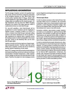
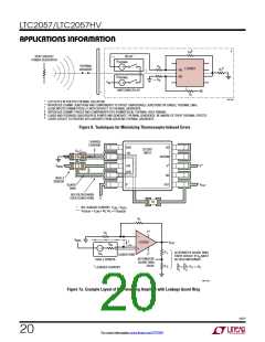
In order to minimize thermocouple-induced errors, atten-
tion must be given to circuit board layout and component
selection. It is good practice to minimize the number of
junctionsintheamplifier’sinputsignalpathandavoidcon-
nectors, sockets, switches, andrelayswheneverpossible.
If such components are required, they should be selected
for low thermal EMF characteristics. Furthermore, the
number, type, and layout of junctions should be matched
for both inputs with respect to thermal gradients on the
circuitboard.Doingsomayinvolvedeliberatelyintroducing
dummy junctions to offset unavoidable junctions.
Injection currents from the two inputs are of equal magni-
tude but opposite direction. Therefore, input bias current
effects due to injection currents will not be canceled by
placing matched impedances at both inputs.
Above75°C,leakageoftheESDprotectiondiodesbeginsto
dominate the input bias current and continues to increase
exponentially at elevated temperatures. Unlike injection
current,leakagecurrentsareinthesamedirectionforboth
inputs. Therefore, the output error due to leakage currents
100
3.0
2.8
SLOPE ≈ 1.5µV/°C
BELOW 25°C
2.6
2.4
2.2
2.0
50
64% SN/36% Pb
1.8
1.6
1.4
1.2
60% Cd/40% SN
0
SLOPE ≈ 160nV/°C
BELOW 25°C
1.0
0.800
0.600
0.400
0.200
0
–50
–100
35
0
10
20
30
40
50
25
30
40
45
SOLDER-COPPER JUNCTION DIFFERENTIAL TEMPERATURE
TEMPERATURE (°C)
SOURCE: NEW ELECTRONICS 02-06-77
2057 F04
2057 F05
Figure 4. Thermal EMF Generated by Two Copper Wires
From Different Manufacturers
Figure 5. Solder-Copper Thermal EMFs
2057f
19
For more information www.linear.com/LTC2057

 LINEAR_DIMENSIONS [ Linear Dimensions ]