LTC2057/LTC2057HV
applicaTions inForMaTion
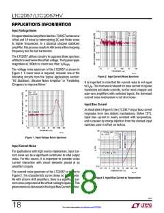
Input Voltage Noise
0.25
0.20
0.15
0.01
0.05
0
A
V
= +11
V
S
=
2.5
ChopperstabilizedamplifiersliketheLTC2057achievelow
offset and 1/f noise by heterodyning DC and flicker noise
to higher frequencies. In a classical chopper stabilized
amplifier, thisprocessresultsinidletonesatthechopping
frequency and its odd harmonics.
NO 1/f NOISE
The LTC2057 utilizes circuitry to suppress these spurious
artifacts to well below the offset voltage. The typical ripple
magnitude at 100kHz is much less than 1µV
.
RMS
0.1
10
FREQUENCY (Hz)
1k
10k
1
100
The voltage noise spectrum of the LTC2057 is shown in
Figure 1. If lower noise is required, consider one of the
following circuits from the Typical Applications section:
"DC Stabilized, Ultralow Noise Amplifier" or "Paralleling
Choppers to Improve Noise."
2057 F02
Figure 2. Input Current Noise Spectrum
It is important to note that the current noise is not equal
to 2 I . This formula is relevant for base current in bipolar
q B
transistors and diode currents, but for most chopper and
auto-zero amplifiers with switched inputs, the dominant
current noise mechanism is not shot noise.
35
A
V
= +11
V
S
=
2.5V
30
25
20
15
10
5
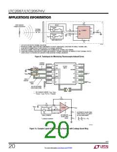
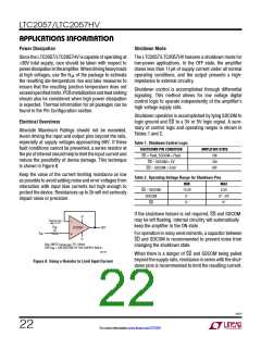
Input Bias Current
As illustrated in Figure 3, the LTC2057’s input bias current
originates from two distinct mechanisms. Below 75°C,
input bias current is nearly constant with temperature,
and is caused by charge injection from the clocked input
switches used in offset correction.
NO 1/f NOISE
0
0.1
10
1k 10k 100k 1M
1
100
FREQUENCY (Hz)
100
1 TYPICAL UNIT
S
2057 F01
V
= 2.5V
Figure 1. Input Voltage Noise Spectrum
10
1
Input Current Noise
For applications with high source impedances, input cur-
rent noise can be a significant contributor to total output
noise. For this reason, it is important to consider noise
current interaction with circuit elements placed at an
amplifier’s inputs.
25°C MAX I SPEC
B
0.1
0.01
–25
0
25
100
125 150
–50
50 75
TEMPERATURE (°C)
The current noise spectrum of the LTC2057 is shown in
Figure 2. The characteristic curve shows no 1/f behavior.
As with all zero-drift amplifiers, there is a significant cur-
rentnoisecomponentattheoffset-nullingfrequency. This
phenomenonisdiscussedintheInputBiasCurrentsection.
2057 F03
Figure 3. Input Bias Current vs Temperature
2057f
18
For more information www.linear.com/LTC2057

 LINEAR_DIMENSIONS [ Linear Dimensions ]