LTC2057/LTC2057HV
applicaTions inForMaTion
Air currents can also lead to thermal gradients and cause
significant noise in measurement systems. It is important
to prevent airflow across sensitive circuits. Doing so will
often reduce thermocouple noise substantially.
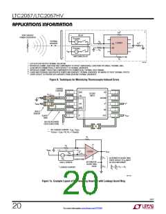
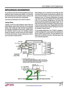
Board leakage can be minimized by encircling the input
connections with a guard ring operated at a potential very
close to that of the inputs. The ring must be tied to a low
impedance node. For inverting configurations, the guard
ring should be tied to the potential of the positive input
(+IN). For non-inverting configurations, the guard ring
shouldbetiedtothepotentialofthenegativeinput(–IN).In
orderforthistechniquetobeeffective,theguardringmust
not be covered by solder mask. Ringing both sides of the
printedcircuitboardmayberequired.SeeFigures7aand7b
for examples of proper layout.
A summary of techniques can be found in Figure 6.
Leakage Effects
Leakage currents into high impedance signal nodes can
easily degrade measurement accuracy of sub-nanoamp
signals. High voltage and high temperature applications
are especially susceptible to these issues. Quality insula-
tion materials should be used, and insulating surfaces
should be cleaned to remove fluxes and other residues.
For humid environments, surface coating may be neces-
sary to provide a moisture barrier.
For low-leakage applications, the LTC2057 is available in
an MS10 package with a special pinout that facilitates the
layout of guard ring structures. The pins adjacent to the
inputs have no internal connection, allowing a guard ring
to be routed through them.
GUARD RING
§
R
F
HIGH-Z SENSOR
LTC2057
MS10
SD
GRD
–IN
V
SDCOM
BIAS
‡
+
+
LEAKAGE
CURRENT
V
V
V
+IN
NC
GRD
NO SOLDER
MASK OVER
GUARD RING
OUT
–
V
OUT
LOW IMPEDANCE
NODE ABSORBS
LEAKAGE CURRENT
–
V
‡
§
NO LEAKAGE CURRENT. V = V
–IN
GRD
AVOID DISSIPATING SIGNIFICANT AMOUNTS OF POWER IN THIS RESISTOR.
IT WILL GENERATE THERMAL GRADIENTS WITH RESPECT TO THE INPUT PINS
AND LEAD TO THERMOCOUPLE-INDUCED ERROR. THERMALLY ISOLATE OR
ALIGN WITH INPUTS IF RESISTOR WILL CAUSE HEATING.
R
F
GUARD RING
HIGH-Z SENSOR
V
BIAS
+
V
V
IN
R
IN
+
–
+
–
LEAKAGE
CURRENT
LTC2057
V
OUT
–
V
LEAKAGE CURRENT IS ABSORBED BY GROUND INSTEAD OF
CAUSING A MEASUREMENT ERROR.
2057 F07b
Figure 7b. Example Layout of Inverting Amplifier with Leakage Guard Ring
2057f
21
For more information www.linear.com/LTC2057

 LINEAR_DIMENSIONS [ Linear Dimensions ]