LTC2057/LTC2057HV
applicaTions inForMaTion
Power Dissipation
Shutdown Mode
Since the LTC2057/LTC2057HV is capable of operating at
>30V total supply, care should be taken with respect to
powerdissipationintheamplifier.Whendrivingheavyloads
The LTC2057/LTC2057HV features a shutdown mode for
low-power applications. In the OFF state, the amplifier
draws less than 11μA of supply current under all normal
operating conditions, and the output presents a high-
impedance to external circuitry.
at high voltages, use the θ of the package to estimate
JA
the resulting die-temperature rise and take measures to
ensure that the resulting junction temperature does not
exceedspecifiedlimits.PCBmetallizationandheatsinking
should also be considered when high power dissipation
is expected. Thermal information for all packages can be
found in the Pin Configuration section.
Shutdown control is accomplished through differential
signaling. This method allows for low voltage digital
control logic to operate independently of the amplifier’s
high voltage supply rails.
Shutdown operation is accomplished by tying SDCOM to
logic ground and SD to a 3V or 5V logic signal. A sum-
mary of control logic and operating ranges is shown in
Tables 1 and 2.
Electrical Overstress
Absolute Maximum Ratings should not be exceeded.
Avoid driving the input and output pins beyond the rails,
especially at supply voltages approaching 60V. If these
fault conditions cannot be prevented, a series resistor at
thepinofinterestshouldhelptolimittheinputcurrentand
reduce the possibility of device damage. This technique
is shown in Figure 8.
Table 1. Shutdown Control Logic
SHUTDOWN PIN CONDITION
SD = Float, SDCOM = Float
SD – SDCOM > 2V
AMPLIFIER STATE
ON
ON
SD – SDCOM < 0.8V
OFF
Keep the value of the current limiting resistance as low
as possible to avoid adding noise and error voltages from
interaction with input bias currents but high enough to
protect the device. Resistances up to 2k will not seriously
impact noise or precision.
Table 2. Operating Voltage Range for Shutdown Pins
MIN
MAX
SD – SDCOM
SDCOM
SD
–0.2V
5.2V
–
+
V
V –2V
–
+
V
V
If the shutdown feature is not required, SD and SDCOM
may be left floating. Internal circuitry will automatically
keep the amplifier in the ON state.
For operation in noisy environments, a capacitor between
SD and SDCOM is recommended to prevent noise from
changing the shutdown state.
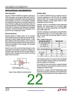
+
V
I
OVERLOAD
–
R
IN
LTC2057
OUT
1k
V
+
IN
–
V
R
IN
LIMITS I
TO <10mA
OVERLOAD
FOR V < 10V OUTSIDE OF THE SUPPLY RAILS.
IN
2057 F08
When there is a danger of SD and SDCOM being pulled
beyond the supply rails, resistance in series with the shut-
down pins is recommended to limit the resulting current.
Figure 8. Using a Resistor to Limit Input Current
2057f
22
For more information www.linear.com/LTC2057

 LINEAR_DIMENSIONS [ Linear Dimensions ]