AN10E40 Data Manual
3
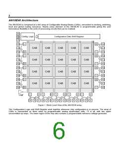
The Configurable Analog Block
The basic building block of the AN10E40 is the Configurable Analog Block. Each CAB is an op-amp surrounded by
capacitor banks, local routing resources, local switching and clocking resources, and global connection points. This
collection of hardware enables the CAB to perform many of the functions that could be achieved using an op-amp
and conventional passive components. All analog processing is accomplished with this switched capacitor circuit.
A Quick Review of Switched Capacitor Circuits
There are many excellent texts available which dive deeply into the details of sampled systems and MOS switch
capacitor circuit theory. The math gets very complex and may have kept you away from switched capacitor circuits
in the past. The good news is that the AnadigmDesigner software for Anadigm devices shields you from all the
complexities of using switched capacitor designs. Still though, it can be useful to review briefly how switched
capacitor circuits operate to eliminate the fear of the unknown.
Consider the following two circuits.
1
2
1
2
R
+
V1
-
+
V2
-
+
V1
-
+
V2
-
C
Conventional Circuit
Switched Capacitor Circuit
Figure 2. Switched Capacitor vs. Conventional Circuit
In the Figure 2, two circuits are shown that can both do the same job. The conventional circuit moves current
around the loop through the resistor. The amount of current of course is a function of the difference between V1
and V2 and the value of R.
The switched capacitor version of the circuit does the same job, but in a different way. With the switch in position 1,
charge moves from the V1 source to the capacitor C, when the switch is moved over to position 2, charge is then
moved from C to V2. As the switch is thrown back and forth, recognize that charge is moving over time, in other
words - current. The faster you throw the switch (and/or the bigger the capacitor is) the more current flows. Unlike
the conventional circuit, simply reprogramming the switching clock rate or the size of the capacitor allows you to
adjust the “resistance” between nodes 1 and 2.
Of course, since this is a sampled system you have to keep in mind the frequency of the signal that is being
processed by the circuit and the frequency at which it is being sampled (or switched). For signals with frequency
content constrained significantly below the sampling frequency the switched capacitor circuit works just like the
conventional circuit. In all cases, the sampling rate should be at least twice as high as the highest frequency of the
signal being processed.

 LATTICE [ LATTICE SEMICONDUCTOR ]