6
externally, the design software allows you to disable the on-chip VMR generator and instead drive the VMR pin
from off chip.
The Bandgap Reference Generator provides a nominal 2.5 V reference signal. Cext is a filtering cap used to quiet
any possible switching noise from getting coupled into this important reference voltage.
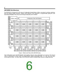
Analog Input Output Cell
The AN10E40 has a flexible analog IO cell that allows you to connect directly into the core’s internal circuitry, buffer
input and output signals to/from the core, and using very few external components, construct a Sallen-Key filter.
I
O
X
Y
Z
Figure 5. Analog Input Output Cell
The “I” and “O” pad designations are Input and Output; these names are relative to the IO Cell itself.
The most common configuration for use as an input is to leave the switch open and power up the buffer. Drive Y
with an external signal and connect O to an IPmodule's input. X and Z should be left unloaded.
The most common configuration for use as an output is to close the switch and power up the buffer. Drive I with an
IPmodule's output and connect an external load to Z. X and Y should be left unloaded.
Under certain circumstances it may be advantageous to leave the switch open and the buffer powered down. For
example, a single Input Output Cell can be used to simultaneously bring a pair of signals in and out of the array. I to
X is an output path from the array, and Z to O is an input path into the array. In doing so however, the external
signal driving Z will be loaded with the input impedance of the IPmodule connected to. This impedance is a function
of the IPmodule's clock speed and input capacitor size. Likewise, the user must stay alert to the external loading of
X which can affect the driving IPmodule's performance.
Another situation which might warrant such direct connections into the array is when your design's input stage will
not tolerate the non-zero offset voltage associated with an input buffer.
Sallen Key Filtering
The flexibility of the IO cell is best appreciated when considering the construction of Sallen-Key filters. Since the
array is based on switched capacitor circuits, your output signal may have unwanted switching noise present. Also,
since this is a sampled data system, some care should be taken to band limit input signals to avoid aliasing
artifacts. Sallen-Key filters are useful for filtering such frequency components out. The AN10E40 IO cells are
uniquely designed to facilitate easy construction of such filters.
The detailed derivation of the math and complete explanation of the theory of operation of these filters would be
better served by another dedicated document, however we are pleased to present the general circuit diagrams for
such filters and will instead refer you to Application Note 010. Also, there are quite a number of excellent analog
filter design tools currently on the market. The major advantage in using such a software package is that most of
them will implement the filter using standard value components, whereas the traditional cook book equation
approach often results in unrealistic component values. One good example of a filter design tool is Filter Wiz LE.
This effective and highly affordable PC based design tool is available on line from www.schematica.com.
For all such filters, as for all external ceramic capacitors in the signal path, only NPO or COG ceramic materials are
recommended (for better voltage coefficient). X7R or similar material can add noticeable distortion to the signal.

 LATTICE [ LATTICE SEMICONDUCTOR ]