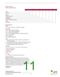
Modifications
With Spring Washer and Friction Ring
These connectors feature a spring washer and a friction ring
under the coupling nut.
(only for CA......-B)
01
02
03
04
– metric crimp contacts
– adapter for heat shrink boots AWG crimp contacts
– adapter for heat shrink boots, metric crimp contacts
Advantage
Improved resistance to vibration
–
rear mount, thread holes in flange, metric crimp
contacts (CA3102 only)
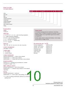
How to order
Delete “31” from standard part number and then insert “W”
after Class E, F or R.
05
– rear mount, through holes in flange, (CA3100, CA
3102, rear mounting CA 20, TBF)
06
08
09
– adaptor for heat shrink boots, solder pot contacts
Example: CA06EW10SL-3P-B-14
–
angular endbell, thread holes in flange (for CA3100 only)
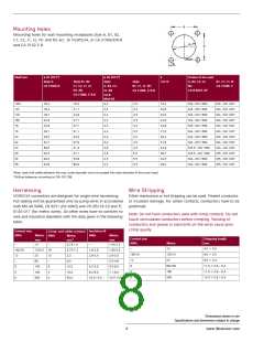
The connectors acc. to VG95234 are generally delivered with
spring washer.
– angular endbell, through holes in flange (for CA3100
only)
13
14
15
32
41
109
– shielded version, solder pot contacts
– shielded version, metric crimp contacts
– shielded version, AWG crimp contacts
– shielded version, reduced cable entry diameter
– grounding spring on barrel
– F80 contacts, rear mount, thread holes in flange (for
CA3102 only)
– rear mount, thread holes in flange (CA3102 only),
solder pot contacts
Additional Connector Options
CA3100E-B-02/03/06
Adapter for heat shrink boot
CA3100E-B-13/14/15
Adapter for shielded cables
CA02L-B
Receptacle with PCB solder contacts
111
F80
– AWG crimp contacts
– gold plated contact, see pages 54-55
– Zinc cobalt black plating
CA20L-B
A176
A232
A233
A239
A240
F42
Rear mount receptacle with PCB solder contacts
CA06EH*
– Zinc cobalt green plating
H stands for High temperature FKM insulator and sealing material
– Zinc cobalt black plating, VG approved
– Zinc Nickel plating, blue grey plating
– less grommet and backshell
CA07A-B
Jam nut receptacle
F0
– less contacts, contacts to be ordered separately,
see pages 54-55
CA00EP-B-TL*
TINEL-LOCK adapter
CA06EW-B-TLXX*
TINEL-LOCK adapter
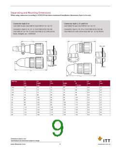
Connector style D or
Important!
CA3106E-B and CA3106F-B CA3106F-B-13/-14/-15
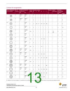
VG contact arrangements are restricted. Only those
Connector style G, M, R1 or CA3106E-B-02/-03/-06
layouts listed in VG95234 standard are allowed. See the
CA3106E-B-13/-14/-15 and CA3106E-B-32 with shrink boot,
following pages for VG permitted layouts and contact
straight, acc. VG95343
CA06PG/ME
PG or Metric gland adapter
*Consult factory for availability
arrangements.
Further details about contact terminations / wire ranges
can be found on pages 54-59.
Dimensions shown in mm
Specifications and dimensions subject to change
12
www.ittcannon.com

 ITT [ ITT Cannon ]