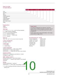
How to order
VG Order reference
VG95234
A
–
32–6
S
1
N
1
H
Series
Shell style
Dash
Shell size
Contact arrangement
Contact type
Contact termination
Insulator position
With / without contacts
Plating
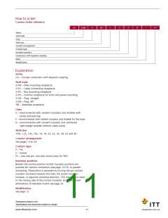
Explanation
Series
VG95234
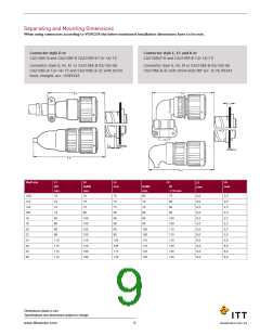
Connector style D or
CA3106E-B and CA3106F-B CA3106F-B-13/-14/-15
Important!
VG contact arrangements are restricted. Only those
Connector style G, M, R1 or CA3106E-B-02/-03/-06
layouts listed in VG95234 standard are allowed. See the
Shell style
CA3106E-B-13/-14/-15 and CA3106E-B-32 with shrink boot,
following pages for VG permitted layouts and contact
J1, J2, N1, N2, S1, U1, U2 – wall mounting receptacle
F, V – cable connection receptacle
A, B1, B2 – box mounting receptacle
C1, C2 – bulkhead receptacle
D, G, H, L, M, R1, T – straight plug
E, E1, K – plug 90°
straight, acc. VG95343
arrangements.
Further details about contact terminations / wire ranges
can be found on pages 54-59.
Accessories acc. to VG
Shell size
Dummy receptacles
Gaskets, front mount
Gaskets, rear mount
Protecting caps
Protecting caps
Cable clamps
VG95234 BOD
VG95234 DA
VG95234 DH
VG95234 KR
VG95234 KB
VG95234 KK
VG95234 KT
10SL, 14S, 16S, 16, 18, 20, 22, 24, 28, 32 and 36
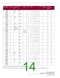
Contact arrangement
See pages 13 to 26
Contact type
P – Pin contact
S – Socket contact
Bushing
Contact termination
Without identification = metric crimp contacts
Identification ‘1’ = AWG crimp contacts
Identification ‘2’ = mixed AWG and metric crimp contacts
Insulator position
Positions N, X, Y allowed only, see details on ‘contact
arrangement’ pages 13-23
With / without contacts
Without identification = with crimp contacts
Identification ‘1’ = without crimp contacts, to be ordered
separately
Plating
Without identification = cadmium
Identification ‘H’ = RoHS, black, ZnCo plating, VG approved
* ‘H’ is the VG plating modification identical to commercial
plating A239
Dimensions shown in mm
Specifications and dimensions subject to change
10
www.ittcannon.com

 ITT [ ITT Cannon ]