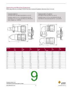
Separating and Mounting Dimensions
When using connectors according to VG95234 the below mentioned installation dimensions have to be met.
Connector style D or
Connector style D or
CA3106E-B and CA3106F-B CA3106F-B-13/-14/-15
CA3106E-B and CA3106F-B CA3106F-B-13/-14/-15
Connector style D or
Connector style E, E1 and K or
CA3106E-B and CA3106F-B CA3106F-B-13/-14/-15
Connector style G, M, R1 or CA3106E-B-02/-03/-06
CA3108E/F-B and CA3108F-B-13/-14/-15
Connector style G, M, R1 or CA3106E-B-02/-03/-06
CA3106E-B-13/-14/-15 and CA3106E-B-32 with shrink boot,
CA3106E-B-13/-14/-15 and CA3106E-B-32 with shrink boot,
straight, acc. VG95343
CA3106E-B-32 with shrink boot 90° acc. to VG 95343
Connector style G, M, R1 or CA3106E-B-02/-03/-06
Connector style G, M, R1or CA3106E-B-02/-03/-06
straight, acc. VG95343
CA3106E-B-13/-14/-15 and CA3106E-B-32 with shrink
boot, straight, acc. VG95343
Shell size
L1
(D)
min.
L2
(G/M)
min.
L3
min.
L4
R1
+10 mm
L5
max
L6
max
(G/M)
min.
10SL
12S
14S
16S
16
70
70
70
65
75
8,0
8,0
8,0
8,0
6,5
8,0
8,0
8,0
8,0
9,0
9,0
9,0
3,5
3,5
3,5
3,5
3,5
3,5
3,5
3,5
5,0
5,0
6,0
6,0
70
75
75
70
80
70
75
75
70
80
70
90
80
80
90
80
100
100
100
100
120
120
180
190
90
90
100
100
110
110
120
120
130
140
18
90
90
90
20
90
95
100
100
110
110
120
130
22
90
95
24
110
110
110
110
105
105
115
120
28
32
36
Dimensions shown in mm
Specifications and dimensions subject to change
www.ittcannon.com
9

 ITT [ ITT Cannon ]