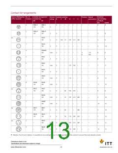
View on Mating face No. of
Contact arrangement
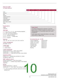
Service
rating
Insulator position
Position Special
Insulator
of Pin Insulator
Contacts Contact size
N
V
W
X
Y
Z
polarization (g) including
contacts
VG
CA
Pin
Socket
3
4
3
2
1
2
10
2
4
3
1
1
8
7
16-7
15
16-7
16
2
1
A
A
A
A
A
A
0
0
0
0
0
0
0
0
0
0
0
0
0
0
–
–
–
–
–
–
–
–
–
–
–
–
–
–
80
35
90
35
–
110 250 280
110 250 325
–
–
–
–
–
–
–
–
–
–
–
–
–
–
–
–
–
–
–
–
–
–
–
–
–
–
–
–
16
25
20
24
17
28
17
37
22
30
25
32
25
30
30
100
8
16-9
12
2
2
–
13
17
11
24
11
24
13
19
15
24
16
18
18
16
16-10
16-10
12
♦
25
180 270
–
16-11
–
12
110 250 325
16-12
16-12
160
4
–
–
–
16A11
16A11
25 (socket)
12
35
70
35
35
80
–
110 250 325
145 215* 290
110 250 325
110 250 325
110 250 280
25A (pin) short
18-1
18-1
A (B, C,
♦
15
16
F, G) Instr.
(all others)
18-3
–
–
–
–
–
–
12
D
18-4
16
D
18-5
12
2
1
D
16
18-6
4
D
–
–
–
–
–
–
–
18-7
8
D
–
–
18-8
12
1
7
A
70
80
290
16
18-9
25
18-9
12
2
5
Instr.
110 250 280
15
16
18-10
12
4
5
–
A
A
0
0
–
–
–
–
120 240
170 265
–
–
–
–
–
–
13
31
22
40
18-11
18-11
25
12
6
–
18-12
A
0
–
80
–
–
280
–
–
15
25
16
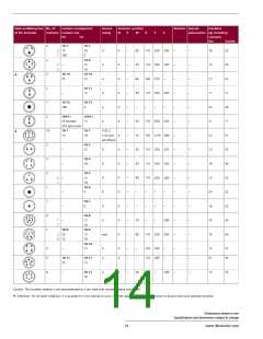
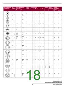
Caution: This insulator rotation is not recommended as it can mate with normal rotation connectors.
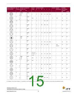
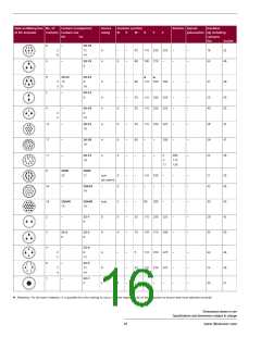
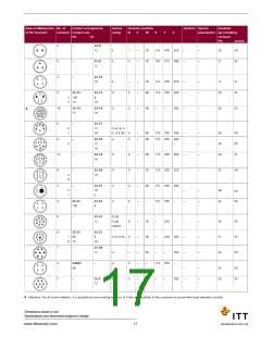
♦ Attention: For all insert rotations, it is possible for miss-mating to occur. It is the responsibility of the customer to ensure they have selected correctly.
Dimensions shown in mm
Specifications and dimensions subject to change
14
www.ittcannon.com

 ITT [ ITT Cannon ]