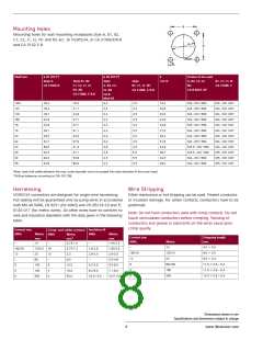
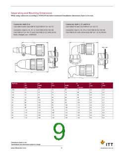
Mounting Holes
Mounting holes for wall mounting receptacles style A, B1, B2,
C1, C2, J1, J2, N1 and N2 acc. to VG95234, or CA 3100E/F/R-B
and CA 3102 E-B.
Shell size
ø d1 (H12*)
Style A
CA 3102E-B
ø d2 (H13*)
Style
A, B2, C2,
J2, N2
E
Screws to be used
A, B2, C2, J2,
N2
Style B1, B2
C1, C2, J1, J2
N1, N2
Style
B1, C1, J1, N1
CA 3100E, F, R-B
±0,15
B1, C1, J1, N
CA 3100E, F
CA-B-Mod. 05
CA 3100E, F, R-B
CA-B
Mod-05
3,4
10SL
12S
14S
16S
16
16,4
16,4
19,7
22,9
22,9
26,1
29,5
32,7
36,0
42,0
48,3
54,6
18,5
21,7
24,9
27,7
27,7
31,1
34,5
37,8
41,3
47,1
53,8
60,0
4,5
4,5
4,5
4,5
4,5
4,5
4,5
4,5
4,5
5,5
5,5
5,5
18,2
20,6
23,0
24,6
24,6
27,0
29,4
31,8
34,9
39,7
44,5
49,2
M3...ISO 1580
M3...ISO 1580
M3...ISO 1580
M3...ISO 1580
M3...ISO 1580
M3...ISO 1580
M3...ISO 1580
M3...ISO 1580
M3,5...ISO 1580
M3,5...ISO 1580
M4...ISO 1580
M4...ISO 1580
M4...ISO 1207
M4...ISO 1207
M4...ISO 1207
M4...ISO 1207
M4...ISO 1207
M4...ISO 1207
M4...ISO 1207
M4...ISO 1207
M4...ISO 1207
M5...ISO 1207
M5...ISO 1207
M5...ISO 1207
3,4
3,4
3,4
3,4
3,4
3,4
3,4
3,9
3,9
4,5
4,5
18
20
22
24
28
32
36
When used with safety elements the max. outer diameter must not exceed the outer diameter of the screw head.
*Drilling tolerances according to DIN ISO 286.
Harnessing
VG95234 connectors are designed for single wire harnessing.
Wire Stripping
Either mechanical or hot stripping can be used. Prevent conductor
Full sealing will be guaranteed only by using wires in accordance or insulator damage. For solder contacts, conductors have to be
with MIL-W-5086, LN 9251 (for AWG) and VG 95218-20 and TL
6145-011 (for metric wires). All other wires have to conform to
wire and insulation diameters with the data given in the following
table:
pretinned.
Note: Do not twist conductors used with crimp contacts. Do not
touch uninsulated conductors before crimping. Twisting of
conductors and grease or lubricants on the wires cause poor
crimp quality.
Contact size
AWG
Crimp- and solder contacts Insulation Ø
Metric AWG
mm
Metric
mm2
AWG
Metric
mm
Contact size
AWG
Stripping length
mm
Metric
10
–
10
–
0,75-1,0
–
1,45-2,5
–
4,0 + 0,4
16S/16
15S/15 16
0,75-1,5
2,5
1,6-2,8
2,9-3,5
–
1,60-2,8
2,9-3,5
3,5-4,9
5,5-6,5
7,1-9,0
10,5-13,0
16S/16
15S/15
25
6,0 + 0,5
12
–
25
12
–
12
8
6,0 + 0,5
60
6,0
60/100
160
11,0 + 0,8 – 0,4
11,0 + 0,8 – 0,4
13,0 + 0,8 – 0,4
8
100
160
500
8
10,0
16,0
50,0
4,2-5,8
6,2-9,0
10,5-13,0
4
4
4
0
500
0
0
Dimensions shown in mm
Specifications and dimensions subject to change
8
www.ittcannon.com

 ITT [ ITT Cannon ]