X96010
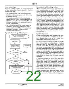
Figure 17. Byte Write Sequence
Write
S
t
a
r
Signals from
the Master
S
t
o
p
Data
Byte
Address
Byte
Slave
Address
t
Signal at SDA
10 1 0
0
Signals from
the Slave
A
C
K
A
C
K
A
C
K
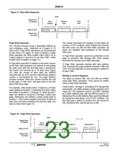
Page Write Operation
The master terminates the loading of Data Bytes by
issuing a STOP condition, which initiates the nonvola-
tile write cycle. As with the Byte Write operation, all
inputs are disabled until completion of the internal
write cycle.
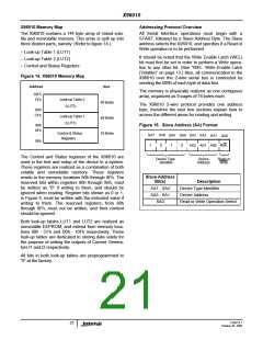
The 144-byte memory array is physically realized as
one contiguous array, organized as 9 pages of 16
bytes each. “Page Write” operations can be performed
to any of the LUT pages. In order to perform a Page
Write operation the Write Enable Latch (WEL) bit in
Control register 6 must first be set (See “WEL: Write
Enable Latch (Volatile)” on page 13.)
A Page Write operation cannot be performed on the
page at locations 80h through 8Fh. Next section
describes the special cases within that page.
A Page Write operation is initiated in the same manner
as the byte write operation; but instead of terminating
the write cycle after the first data byte is transferred,
the master can transmit up to 16 bytes (See Figure
18). After the receipt of each byte, the X96010
responds with an ACK, and the internal byte address
counter is incremented by one. The page address
remains constant. When the counter reaches the end
of the page, it “rolls over” and goes back to the first
byte of the same page.
A Page Write operation starting with byte address
FFh, accesses the page between locations 100h and
10Fh. The first data byte of such operation is written to
location 100h.
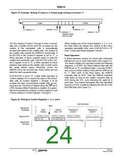
Writing to Control Registers
The bytes at location 80h, 85h and 86h are written
using Byte Write operations. They cannot be written
using a Page Write operation.
Control bytes 1 through 4, at locations 81h through 84h
respectively, are written during a single operation (See
Figure 20). The sequence must be: a START, followed
by a Slave Address byte, with the R/W bit equal to “0”,
followed by 81h as the Address Byte, and then followed
by exactly four Data Bytes, and a STOP condition. The
first data byte is written to location 81h, the second to
82h, the third to 83h, and the last one to 84h.
For example, if the master writes 12 bytes to a 16-byte
page starting at location 11 (decimal), the first 5 bytes
are written to locations 11 through 15, while the last 7
bytes are written to locations 0 through 6 within that
page. Afterwards, the address counter would point to
location 7. If the master supplies more than 16 bytes of
data, then new data overwrites the previous data, one
byte at a time (See Figure 19).
Figure 18. Page Write Operation
Write
2 < n < 16
S
Signals from
t
S
t
o
p
the Master
Address
Byte
Slave
Address
a
r
t
Data Byte (1)
Data Byte (n)
Signal at SDA
10 1 0
0
Signals from
the Slave
A
C
K
A
C
K
A
C
K
A
C
K
FN8214.1
23
October 25, 2005

 INTERSIL [ Intersil ]