X9428
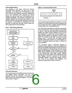
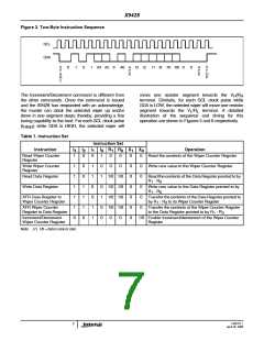
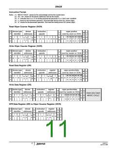
Figure 3. Two-Byte Instruction Sequence
SCL
SDA
S
T
A
R
T
0
1
0
1
A3 A2
0
A0
A
C
K
I3 I2
I1 I0 R1 R0
0
0
A
C
K
S
T
O
P
The Increment/Decrement command is different from
the other commands. Once the command is issued
and the X9428 has responded with an acknowledge,
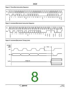
the master can clock the selected wiper up and/or
down in one segment steps; thereby, providing a fine
tuning capability to the host. For each SCL clock pulse
move one resistor segment towards the V /R
H H
terminal. Similarly, for each SCL clock pulse while
SDA is LOW, the selected wiper will move one resistor
segment towards the V /R terminal. A detailed
L
L
illustration of the sequence and timing for this
operation are shown in Figures 5 and 6 respectively.
(t
) while SDA is HIGH, the selected wiper will
HIGH
Table 1. Instruction Set
Instruction Set
Instruction
I
I
I
I
R
R
X
X
0
Operation
3
2
1
0
1
0
1
Read Wiper Counter
Register
1
0
0
0
1
1
1
0
0
1
0
0
0
0
Read the contents of the Wiper Counter Register
Write Wiper Counter
Register
1
1
1
1
1
0
1
1
0
0
1
1
0
1
0
1
0
0
0
0
0
0
0
0
0
0
0
0
0
0
0
Write new value to the Wiper Counter Register
Read Data Register
1/0 1/0
1/0 1/0
1/0 1/0
1/0 1/0
Read the contents of the Data Register pointed to by
R - R
1
0
Write Data Register
Write new value to the Data Register pointed to by
R - R
1
0
XFR Data Register to
Wiper Counter Register
Transfer the contents of the Data Register pointed to
by R - R to its Wiper Counter Register
1
0
XFR Wiper Counter
Register to Data Register
Transfer the contents of the Wiper Counter Register
to the Data Register pointed to by R - R
1
0
Increment/Decrement
Wiper Counter Register
0
0
1/0 Enable Increment/decrement of the Wiper Counter
Register
Note: (7) 1/0 = data is one or zero
FN8197.1
April 26, 2006
7

 INTERSIL [ Intersil ]