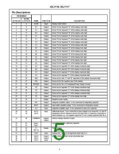
ICL7116, ICL7117
a
a
a
f
f
f
a
b
b
b
g
g
g
c
e
e
e
c
c
c
b
d
d
d
7
7
7
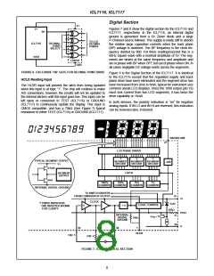
SEGMENT
DECODE
SEGMENT
DECODE
SEGMENT
DECODE
TYPICAL SEGMENT OUTPUT
V+
LATCH
0.5mA
TO
SEGMENT
1000’s
COUNTER
100’s
COUNTER
10’s
COUNTER
1’s
COUNTER
8mA
TO SWITCH DRIVERS
35
37
FROM COMPARATOR OUTPUT
DIGITAL GROUND
V+
V+
CLOCK
TEST
†
÷4
LOGIC CONTROL
500Ω
† THREE INVERTERS
ONE INVERTER SHOWN
FOR CLARITY
DIGITAL
GROUND
21
70kΩ
40
39
38
1
HLDR
OSC 1
OSC 3
OSC 2
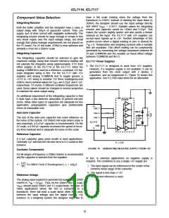
FIGURE 8. ICL7117 DIGITAL SECTION
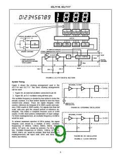
System Timing
INTERNAL TO PART
Figure 9 shows the clocking arrangement used in the
ICL7116 and ICL7117. Two basic clocking arrangements
can be used:
÷4
CLOCK
1. Figure 9A, an external oscillator connected to pin 40.
2. Figure 9B, an R-C oscillator using all three pins.
40
39
38
The oscillator frequency is divided by four before it clocks the
decade counters. It is then further divided to form the three
convert-cycle phases. These are signal integrate (1000
counts), reference de-integrate (0 to 2000 counts) and auto-
zero (1000 counts to 3000 counts). For signals less than full
scale, auto-zero gets the unused portion of reference de-
integrate. This makes a complete measure cycle of 4,000
counts (16,000 clock pulses) independent of input voltage.
For three readings/second, an oscillator frequency of 48kHz
would be used.
GND ICL7117
TEST ICL7116
FIGURE 9A. EXTERNAL OSCILLATOR
INTERNAL TO PART
÷4
CLOCK
To achieve maximum rejection of 60Hz pickup, the signal
integrate cycle should be a multiple of 60Hz. Oscillator
40
39
R
38
C
frequencies of 240kHz, 120kHz, 80kHz, 60kHz, 48kHz,
1
40kHz, 33 / kHz, etc. should be selected. For 50Hz rejec-
3
2
tion, Oscillator frequencies of 200kHz, 100kHz, 66 / kHz,
3
50kHz, 40kHz, etc. would be suitable. Note that 40kHz (2.5
readings/second) will reject both 50Hz and 60Hz (also
400Hz and 440Hz).
FIGURE 9B. RC OSCILLATOR
FIGURE 9. CLOCK CIRCUITS
9

 INTERSIL [ Intersil ]