ICL7116, ICL7117
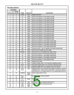
Pin Descriptions
PIN NUMBER
44 PIN
40 PIN DIP FLATPACK
NAME
HLDR
D1
FUNCTION
Input
DESCRIPTION
1
8
Display Hold Control.
2
9
Output
Output
Output
Output
Output
Output
Output
Output
Output
Output
Output
Output
Output
Output
Output
Output
Output
Output
Output
Output
Output
Output
Output
Output
Supply
Output
Output
Input
Driver Pin for Segment “D” of the display units digit.
Driver Pin for Segment “C” of the display units digit.
Driver Pin for Segment “B” of the display units digit.
Driver Pin for Segment “A” of the display units digit.
Driver Pin for Segment “F” of the display units digit.
Driver Pin for Segment “G” of the display units digit.
Driver Pin for Segment “E” of the display units digit.
Driver Pin for Segment “D” of the display tens digit.
Driver Pin for Segment “C” of the display tens digit.
Driver Pin for Segment “B” of the display tens digit.
Driver Pin for Segment “A” of the display tens digit.
Driver Pin for Segment “F” of the display tens digit.
Driver Pin for Segment “E” of the display tens digit.
Driver pin for segment “D” of the display hundreds digit.
Driver pin for segment “B” of the display hundreds digit.
Driver pin for segment “F” of the display hundreds digit.
Driver pin for segment “E” of the display hundreds digit.
Driver pin for both “A” and “B” segments of the display thousands digit.
Driver pin for the negative sign of the display.
3
10
11
12
13
14
15
16
17
18
19
20
21
22
23
24
25
26
27
28
29
30
31
32
34
35
36
37
C1
4
B1
5
A1
6
F1
7
G1
8
E1
9
D2
10
11
12
13
14
15
16
17
18
19
20
21
22
23
24
25
26
27
28
29
C2
B2
A2
F2
E2
D3
B3
F3
E3
AB4
POL
BP/GND
G3
Driver pin for the LCD backplane/Power Supply Ground.
Driver pin for segment “G” of the display hundreds digit.
Driver pin for segment “A” of the display hundreds digit.
Driver pin for segment “C” of the display hundreds digit.
Driver pin for segment “G” of the display tens digit.
Negative power supply.
A3
C3
G2
V-
INT
BUFF
A-Z
Integrator amplifier output. To be connected to integrating capacitor.
Input buffer amplifier output. To be connected to integrating resistor.
Integrator amplifier input. To be connected to auto-zero capacitor.
30
31
38
39
IN LO
IN HI
Input
Differential inputs. To be connected to input voltage to be measured. LO and HI
designators are for reference and do not imply that LO should be connected to
lower potential, e.g., for negative inputs IN LO has a higher potential than IN HI.
32
40
COMMON
Supply/
Output
Internal voltage reference output.
Connection pins for reference capacitor.
Power Supply.
33
34
41
42
C
-
REF
C
+
REF
35
36
43
44
V+
Supply
Input
REF HI
TEST
37
3
Display test. Turns on all segments when tied to V+.
Device clock generator circuit connection pins.
38
39
40
4
6
7
OSC3
OSC2
OSC1
Output
Output
Input
5

 INTERSIL [ Intersil ]