ICL7116, ICL7117
Typical Applications (Continued)
OSC 1 40
OSC 1 40
OSC 2 39
OSC 3 38
TEST 37
REF HI 36
V+ 35
100kΩ
100kΩ
OSC 2 39
OSC 3 38
SET V
= 1.000V
SET V
REF
REF
100pF
100pF
TEST 37
= 100mV
REF HI 36
+5V
V+ 35
V +
25kΩ
24kΩ
1kΩ 10kΩ 15kΩ
C
C
34
33
C
34
33
REF
REF
REF
0.1µF
0.1µF
C
REF
1.2V (ICL8069)
COMMON 32
IN HI 31
IN LO 30
A-Z 29
BUFF 28
INT 27
COMMON 32
IN HI 31
IN LO 30
A-Z 29
BUFF 28
INT 27
1MΩ
0.01µF
1MΩ
+
+
IN
IN
0.01µF
0.047µF
470kΩ
-
-
0.47µF
47kΩ
0.22µF
0.22µF
-
V - 26
V
V - 26
G2 25
G2 25
C3 24
C3 24
TO DISPLAY
TO DISPLAY
A3 23
A3 23
G3 22
G3 22
GND 21
GND 21
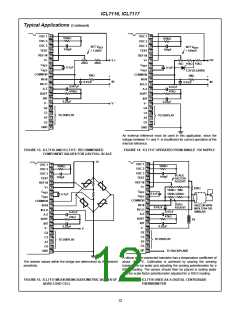
An external reference must be used in this application, since the
voltage between V+ and V- is insufficient for correct operation of the
internal reference.
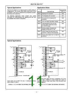
FIGURE 13. ICL7116 AND ICL7117: RECOMMENDED
FIGURE 14. ICL7117 OPERATED FROM SINGLE +5V SUPPLY
COMPONENT VALUES FOR 2.0V FULL SCALE
V+
OSC 1 40
OSC 1 40
100kΩ
100kΩ
OSC 2 39
OSC 2 39
OSC 3 38
OSC 3 38
SCALE
100pF
TEST 37
100pF
TEST 37
FACTOR
ADJUST
REF HI 36
REF HI 36
V+ 35
V+ 35
22kΩ
100kΩ 1MΩ
C
C
34
33
C
C
34
33
REF
REF
REF
0.1µF
100kΩ 220kΩ
0.1µF
REF
COMMON 32
IN HI 31
IN LO 30
A-Z 29
BUFF 28
INT 27
V - 26
COMMON 32
IN HI 31
IN LO 30
A-Z 29
ZERO
ADJUST
SILICON NPN
MPS 3704 OR
SIMILAR
0.01µF
0.47µF
47kΩ
0.47µF
47kΩ
BUFF 28
INT 27
9V
0.22µF
0.22µF
V - 26
V
G2 25
G2 25
C3 24
C3 24
TO DISPLAY
TO DISPLAY
A3 23
A3 23
G3 22
G3 22
BP 21
GND 21
TO BACKPLANE
A silicon diode-connected transistor has a temperature coefficient of
o
The resistor values within the bridge are determined by the desired
sensitivity.
about -2mV/ C. Calibration is achieved by placing the sensing
transistor in ice water and adjusting the zeroing potentiometer for a
000.0 reading. The sensor should then be placed in boiling water
and the scale-factor potentiometer adjusted for a 100.0 reading.
FIGURE 15. ICL7117 MEASUREING RATIOMETRIC VALUES OF
QUAD LOAD CELL
FIGURE 16. ICL7116 USED AS A DIGITAL CENTIGRADE
THERMOMETER
12

 INTERSIL [ Intersil ]