BBT3821
many TOSA, ROSA and lane-oriented DOM devices have
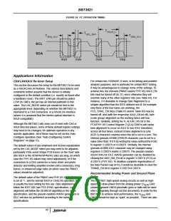
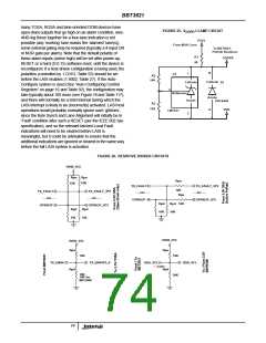
FIGURE 25. V
CLAMP CIRCUIT
P3V3
DDPR
open-drain outputs that go high on an alarm condition, wire-
AND-ing these together for a four-lane indication is not
possible (any ‘working’ lane masks the ‘alarmed’ lane(s)),
some external gating may be required (typically a 4-input OR
or NOR gate per alarm). Note that the default polarity of
these alarm inputs (active high) will be set after power-up,
RESET or a hard (D.0.15) software reset, until the device is
reconfigured. If a host-driven configuration is being used, the
polarities (controlled by 1.C01D, Table 55) should be set
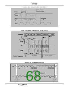
before the LASI enables (1.9002, Table 27). If the Auto-
Configure system is used (See “Auto-Configuring Control
Registers” on page 16 and Table 92), the configuration may
take typically about 100 msec (see Figure 18 and Table 117),
and there will normally be a brief interval during which the
LASI interrupt is likely to be (incorrectly) activated. LASI host
operations would probably normally ignore such ‘glitches’,
since the Byte Synch and Lane Alignment will initially be in
‘Fault’ condition after such a RESET (per the IEEE 802.3ae
specification), and so the relevant latched Local Fault
indications will need to be cleared before LASI is
From MSA Conn
To BBT3821,
Pull-Up Resistors
R1
68
VDDPR
B
1
U1
R2
10K
Cathode
Cathode
D1
3
Reference
Anode
Anode
ZHCS400
VDD
R3
12K
A
LMV431
2
meaningful, but it could be advisable to ensure that the
additional indications are ignored or cleared in the same way
before the full LASI system is activated.
FIGURE 26. RESISTIVE DIVIDER CIRCUITS
RAW_3V3
Rpu Rpu
Rpu
12K
12K
12K
TX_FAULT
---etc.---
OPRXOP
TX_FAULT_3P3
TX_FAULT
---etc.---
TX_FAULT_3P3
---etc.---
Rpu
---etc.---
OPRXOP_3P3
Rpd
10K
Rpd 12K
10K
OPRXOP
OPRXOP_3P3
Rpd
10k
Rpd
10k
RAW_3V3
Rpu
RAW_3V3
Rpu
12K
12K
TX_ENA#
TX_ENA3P3_#
SDA, SCL
---each--
Rpd
SDA, SCL
Rpd
16K
30K
18K for
MIC3000
74

 INTERSIL [ Intersil ]