BBT3821
two further analog supplies, V
and V
for the CMU
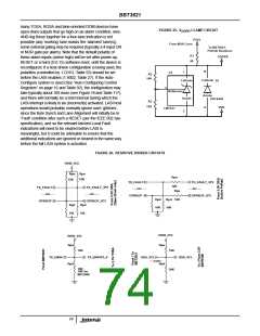
applied faster or earlier than the V
supply, it is
DD
DDAC
DDAV
and VCO respectively. These two also need to be kept quiet.
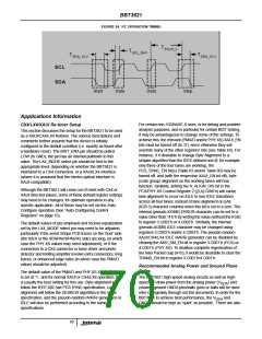
recommended that a limiting clamp be provided to maintain
the Absolute Maximum Rating limits of Table 102. A simple
example of such a clamp is given in Figure 25, using a small
shunt regulator. Since the power dissipation of the regulator
is negligible except during the supply power-up time
difference, no special heat dissipation precautions are
needed.
The V and V voltage requirements of
V
V
DDA, DDAC, DDAV
the standard BBT3821 are all 1.5V (for the Low Power
LX4-only version 1.355V). The ripple noise on the V
DD
DDA#
voltage rails should be as low as possible for best jitter
performance. Therefore, in the layout, each V should be
DDA
decoupled from the main 1.5V(1.4V) supply by means of cut
outs in the power plane, and the power to the individual
XENPAK/XPAK/X2 Interfacing
V
areas supplied through ferrite beads (1A capability is
DDA
The BBT3821 incorporates a number of features that
facilitate interface to the (pin-function-compatible) XENPAK,
XPAK and X2 interfaces. The relevant 3.125Gbps serial lines
in the BBT3821-JH are brought out in exactly the correct
order to be connected to the edge connector, minimizing any
layout problems, and the use of vias, in PCB design.
Furthermore, the BBT3821 device also incorporates the
logic required to handle the TX_ON/OFF and LASI pins, to
recommended). The cut out spacing should be at least 20mil
(0.5mm).
A “quiet” analog ground also enhances the jitter performance
of the BBT3821 as well. A similar cut out in the ground plane
is recommended, to isolate the analog sections from the
digital ones.
2
Recommended Power Supply Decoupling
interface (via an I C bus) with an EEPROM (or similar
For the BBT3821, the decoupling for V
V
V
,
device) to load the NVR space with all the MDIO register
values specified in the XENPAK MSA R3.0 specification
(which are referenced, with only minor OUI-number type
changes in the XPAK and X2 specifications), and to transfer
Digital Optical Monitoring (DOM) information from typical
DDA DD, DDAC
must all be handled individually.
and V
DDAV
V
(1.5V/1.355V) provides power to most of the analog
DDA
circuits as well as the high speed I/Os. The analog power
supply V must have an impedance of less than 0.4Ω
DDA
2
I C-interface devices into the XENPAK (etc.) specified MDIO
from around 50kHz to over 1GHz. This can be achieved by
using one 22µF (1210 case size, Ceramic), and eleven
0.1µF (0402 case size, ceramic), and eleven 0.01µF (0402
case size, ceramic) capacitors in parallel. The 0.01µF and
0.1µF 0402 case size capacitors must be placed right next to
space. If the XP_ENA pin is high at the end of hardware or
2
full MDIO reset, the I C engine will attempt to read whatever
device is on the bus at the A0:00’h address. If it succeeds, it
will read the A0:01’h address, and so on, till it reaches
2
A0:FF’h. If at any point the number of I C Acknowledge
the V
balls as close as possible. Note that the 22µF
DDA
(ACK) failures on any address exceeds the limit set in
register 1.8005’h (see Table 20) the NVR load will fail, and
the result of the operation in 1.8000’h will report the failure.
capacitor must be ceramic for the lowest ESR possible, and
must be of 1210 case size or better to achieve this. The
0.01µF capacitors should be of case size 0402 or better,
offering the lowest ESL to achieve low impedance towards
the GHz range. Also, note that the ground of these
capacitors must be well connected to GNDA.
If a suitable device with 256 bytes at the A0 device address
(either a serial EEPROM device like the Atmel AT24C02A or
a device such as the Micrel MIC3000 or the Dallas
Semiconductor DS1852) is present, the data in it will thus be
transferred to the MDIO register space. Most of this data is
merely copied to the MDIO space, but a few specific items
(listed in Table 22) have additional effects, for example
providing the ‘Package OUI values for 1.14:15, or the DOM
Capability bits in the 1.807A register.
Similarly V
V
(also 1.5V/1.355V) supply the
DDAC and DDAV
frequency (and hence jitter) determining sections of the
BBT3821. They should each be decoupled using one 22µF
ceramic lowest-ESR-possible capacitor, and one each of
0.01µF and 0.1µF. The latter especially should be close to
the respective balls of the device, with a low impedance
trace-path to the device and to GNDA.
If these DOM Capability bits (listed in Table 23) indicate that
the 2-wire bus has a device (again such as the Micrel
MIC3000 or the Dallas Semiconductor DS1852) oriented to
performing the SFF-8472-defined DOM function, the
BBT3821 will attempt to read the data from that device into
the MDIO DOM Alarm and Warning Thresholds registers
(see Table 32), and the current A/D value and flag registers
(see Table 33, Table 36 and Table 37). If the XENPAK DOM
Operation Control and Status Register (see Table 38) is set
appropriately, the DOM current A/D value and flag registers
will be updated periodically from all the DOM device(s), via
the DOM device pointers in Table 54 and Table 55. See "I2C
Interfacing" below for more details.
The V
DD
(1.5V/1.355V) supply is the power rail for the
BBT3821core logic circuit. For this supply, at least three
0.1µF (0402 case size), three 0.01µF (0402 case size) and a
10µF (tantalum or ceramic) capacitor are recommended.
Place the 0.01µF and 0.1µF capacitors as close to the V
balls as possible.
DD
V
(recommended 2.5V or less) is used for certain ESD
DDPR
protection circuits; at least two 0.01µF (0402 case size), and
two 0.1µF (0402 case size) capacitors are recommended.
Place the 0.01µF and 0.1µF capacitors as close to the
V
balls as possible. If the V
supply can be
DDPR
DDPR
71

 INTERSIL [ Intersil ]