BBT3821
supplies), and systems using intermediate supply voltages.
CX4 Interfacing
In general, no problems should occur in any such
The relevant 3.125Gbps serial lines in the BBT3821-JH are
brought out in exactly the correct order to be connected to
the CX4 connector, using either the top layer of the PCB for
striplines, or an inner layer for microstrip lines, without any
necessity for crossing the various leads. There are GNDA
pins between each serial line pair, and special care has been
taken to facilitate the optimal separation of the TX3 and RX3
line pairs. Increasing the PCB trace separation between
these pairs, and adding a strip of GNDA, will decrease the
crosstalk effects, which are normally most severe for this
pair. Note that the CX4 output will not reliably meet the CX4
applications, provided the resistive pull-ups go to no higher
than a nominal 2.6V. However, the BBT3821 is inherently a
very high-speed device, and the falling-edge-rates
generated by the part can be quite high. To avoid problems
with excessive coupling between the MDIO line and the
MDC line, and consequent generation of false clock-edges
on the MDC line, and hence incorrect MDIO operation, the
MDC line has been given a Schmitt trigger input.
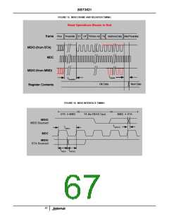
Note that the MDIO registers will not be written till AFTER up
to three additional clocks after the end of a WRITE frame
(see Figure 15). It is recommended that MDC run
continuously, but if this is not possible, extra clocks should
be added after a WRITE. These will count toward the
preamble for the next frame (except when the byte written
caused a Soft Reset, see Figure 17, and extra preambles
may be required).
specification with the V
supplies as low as 1.344V (1.4V-4%), so the Low Power
version device is not recommended for this usage.
V
V
, and V
DDA DD, DDAC DDAV
LX4 Interfacing
In LX4 mode, the serial PMA/PMD outputs are by default set
up without pre-emphasis, since it is anticipated that the laser
driver circuits will be located only a short distance away. This
can be overridden by the Auto-configure capability, if
desired, to accommodate a lossy or long interconnect, and
to provide enhanced high-frequency drive if needed by the
laser driver. Similarly, the receiver inputs are set up by
default without equalization. Again, this can be overridden by
the Auto-configure capability, if desired, to accommodate a
lossy or long interconnect, and to compensate for poor high-
frequency performance in the photodetectors. Under
‘Standard’ part conditions, these signals are XAUI-
compatible. Under the ‘Low Power’ supply voltage
conditions, the output drive may fall below the XAUI
specification. This is normally not a problem for laser drivers,
but if Low Power operation is desired, this should be
checked.
2
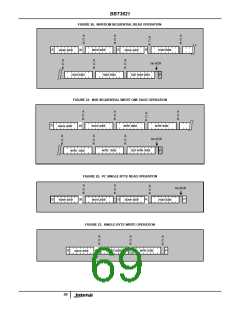
I C Interfacing
2
The I C interface, normally used to provide the NVR
requirements for XENPAK/XPAK/X2 MSA modules, consists
2
of two lines, SCL and SDA. These conform to the I C
2
specification (‘THE I C-BUS SPECIFICATION, Version 2.1’,
at URL
http://www.semiconductors.philips.com/acrobat/literature/93
98/39340011.pdf) for Standard-mode (to 100kHz) and Fast-
mode (to 400kHz) operation. The BBT3821 is a bus master,
and expects to see the NVR EEPROM and/or DOM circuits
as slaves. Particularly if Fast-mode operation is desired, the
capacitance of and coupling between the SCL and SDA lines
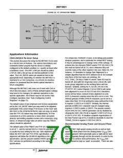
should be minimized. Since these lines are ‘open drain’, the
rise time of the SCL line will inherently stretch the ‘low’ time
of the line, as seen by the BBT3821, due to the effect of the
RC time constant of the pull-up resistor and the line
capacitance. This will slow down the operation of the
Many lasers and laser drivers require setting of the laser
bias and modulation currents, to optimize the performance.
This is frequently done via digitally controlled resistors or
2
interface. If the other I C devices on this bus are 3.3V
2
devices, their V levels should be checked to ensure
IH
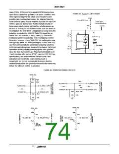
current sources, many of which have I C interfaces for
satisfactory logic operation if the pull-up resistors are taken
to a nominal 2.5V. If they will work from a lower voltage, the
resistors can be taken to any such voltage down to the VDD
level. The above reference includes charts for the values of
the resistors, based on the capacitance of the line, and the
desired clock rate. For the default operation speed of
nominally 100kHz, a value of 5kΩ to 15kΩ will normally be
suitable, while for Fast-mode operation, 2kΩ to 4kΩ will
normally be needed. If a 2.5V supply is not available,
resistive dividers may be used to ensure that the signals on
the BBT3821 lines do not exceed that level. Some examples
are shown in Figure .
setting the values, often as a function of temperature. By
ensuring that the Device Addresses of these circuits are
distinct from those of the NVR, and any separate DOM
2
circuits provided, the I C interface of the BBT3821 can be
used to initialize the setups of these circuits. The technique
described under “Byte Writes to EEPROM space” on
page 19 can always be used in this case. This can be done
after a module is fully assembled, if necessary using one of
the ‘spare’ pins on the XENPAK connector, or a GPIO pin, to
enable writing to the relevant circuits.
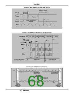
MDIO/MDC Interfacing
The MDIO and MDC lines in the BBT3821 have been
designed to maximize compatibility both with older systems,
that may use logic levels compatible with 3.3V CMOS
designs (such as specified in IEEE 802.3-2002 Clause 22),
and newer systems compatible with the levels specified in
the 10GE specification IEEE 802.3ae-2002 (based on 1.2V
DOM Interfacing
The NVR interface has already been discussed above
(“XENPAK/XPAK/X2 Interfacing” on page 71). The BBT3821
also includes a flexible DOM interface. See “DOM Registers”
on page 16 for details. Most laser drivers and receivers
72

 INTERSIL [ Intersil ]