BBT3821
(TOSA and ROSA) include monitor outputs reflecting the
Laser Bias Current, the Laser Output Power, and/or
Received Optical Power. Some of these analog outputs are
additional 256-byte EEPROM such as an Atmel AT24C02A
will be needed.
Using four of the single-lane devices mentioned previously,
the system can monitor all four lanes. A first download of a
single device would load the full 256-byte space, and the
BBT3821 should then be set in ‘Indirect Mode’ (see Table 51
and "DOM Registers"), with the pointers appropriately reset.
For the MIC3000, three of the four devices should have their
referenced to GND, others to an appropriate V
For use
DD.
in the optional DOM system, these values need to be
converted to digital values, compared with alarm and
warning levels, and made available as both digital values
and as flag registers and alarm signals.
2
Since the WDM 4-lane DOM interface ideally needs to find
‘furthest-out-of-range’ values, it will operate most effectively
using a single DOM control and conversion device. Suitable
parts include the Cygnal C8051F311 device, which can
‘I CADR’ values changed (e.g. to B2, C2 & D2), leaving the
fourth at the default DOM address A2. The NVR space will
be provided by the A0 space in that last device, while the
DOM spaces for each of the four lanes are accessed via the
indirect Device Address pointers in 1.C01B:C’h, which would
be set to A2, B2, C2 & D2 in the above scenario. The
memory address values in 1.C019:A’h would be left at the
default 60’h value. To utilize the DS1852, an EEPROM is
needed for the NVR at the A0 address space, and one lane’s
DS1852 should have the D0h Device Address value at the
A2 default value, and its ASEL pin should be high. The
others (also with ASEL high) should have the D0h values set
to an array of different Device Address values, for instance
B2, C2 & D2 (as in the previous example), or A4, A6 & A8,
and the same values also set in 1.C01B:C’h. A first pass will
read the EEPROM space in A2.00:5F’h from the DS1852
device at A2, followed by the A/D and flag values from
A2.60:75’h, and various other values to A2.7F’h. The space
from A2.80:FF’h depends on the DS1852 Table select byte
(7F’h); if this is 0, the source data is empty; if it is set for
Table 03, the actual Alarm and Warning threshold values will
be returned; if 01 or 02, the various EEPROM banks,
depending on the Access Level set. See the DS1852 data
sheet for details. Subsequent DOM reads performed with
Indirect Access can load the standard XENPAK 4-lane A/D
space from the four DOM devices.
handle the 12 monitored values, 4 V
signal reference
DD
levels, the SCL and SDA signals, and the LASI-driving
TX_FAULT, OPTTEMP, OPTXLBC, OPTXLOP, and
OPRXOP signals. The device includes a 10-bit differential
ADC, a temperature sensor, an onboard clock oscillator, and
2
an I C bus controller (called the SMBUS system by Cygnal),
which should be set up as a slave. The NVR information can
all be stored in the on-board Flash EEPROM memory,
making for a single NVR/DOM/LASI device. If additional I/O
signals are required, the similar C8051F310 has them
available, for an increase in board area. Alternatively, an
analog multiplexer such as the Maxim MAX4694 could be
used to switch inputs between different lanes, under I/O pin
control. A similar series of parts are available from Cyex as
the SLC series. These parts also include DACs for Laser
control functions. If this type of device is used, the BBT3821
should be set up in ‘Direct DOM’ mode (see Table 51 and
"DOM Registers"), and it will then be able to download the
complete DOM block as required.
An alternative is to use a device specifically designed as a
DOM device, such as the Micrel MIC3000 or the
Maxim/Dallas Semiconductor DS1852. Each of these is a
single lane device, and is oriented to fulfilling the
requirements for SFP modules and the SFF-8472
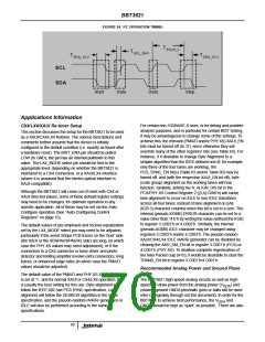
Open drain outputs from the DOM devices can be pulled up
via resistors to V , or any voltage between that and a
DD
specification. Although very similar, the latter has some
small differences from the XENPAK DOM specification,
which can cause problems. If a single device is used, it can
be configured as a single DOM device, typically at device
address A2, and used to monitor, for example, the average
(sum) of the desired values. The thresholds, monitored
values, and alarm and warning flags will conform to the
required behavior for single-lane monitoring (see Note 2 to
Table 27 in section 11.2.6 of the XENPAK R3.0
specification). If the BBT3821 is set up in ‘Direct DOM’ mode
(see Table 51 and "DOM Registers"), the single-lane values
will be transferred to the MDIO register space. Such an
arrangement may be very suitable for use in a CX4 module,
where it could be desirable to measure the temperature,
although the “Laser Bias Current”, “Received Optical
Power”, etc. have no meaning (and “Digital Optical
Monitoring” is a misnomer!). Note that the DS1852 does not
provide a sufficient NVR block for XENPAK, and an
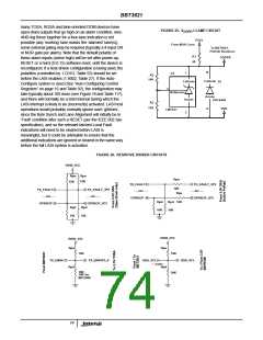
nominal 2.5V. If a 2.5V supply is not available, resistive
dividers may be used to ensure that the signals on the
BBT3821 lines do not exceed that level. Active pullup
devices should have their outputs divided before reaching
the BBT3821 pins. Some examples of each are shown in
Figure .
LASI Interface
The BBT3821 incorporates all the logic needed to control
and enable the full XENPAK/X2/XPAK Link Alarm Status
Interrupt (LASI) system, with several optional incorporated
enhancements. Many of the (specified and optional extra)
inputs are derived from the status registers in the BBT3821
(See “LASI Registers & I/O ” on page 17, and Figure 5), and
the others are derived from a set of input pins (see Table 99)
that would normally be driven by the corresponding status
outputs of the either the TOSA and ROSA devices, or (if
implemented) the DOM devices. The active polarity of these
pins can be controlled via the BBT3821 registers. Since
73

 INTERSIL [ Intersil ]