BBT3821
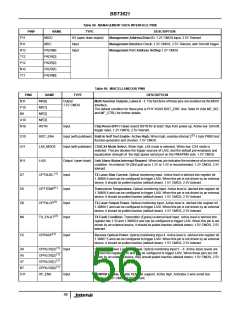
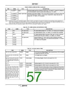
Table 99. MISCELLANEOUS PINS (Continued)
PIN#
NAME
TYPE
DESCRIPTION
(1)
D9
TX_ENC
Input
Transmit enable input from XENPAK module input “TX ON/OFF”. Controls TX_ENA[3:0].
For normal operation, should be pulled active (default up). 1.2V CMOS
(1)
(1)
(1)
(1)
B5
B6
T5
R5
TX_ENA[3]
TX_ENA[2]
TX_ENA[1]
TX_ENA[0]
Output (open drain) Transmit Laser Driver Enables. They are set active only when TX_ENC pin is active and
the corresponding bits in register 1.9 are set low. During RESET stage, these pins are
always low. 1.5V CMOS, 2.5V compatible.
Note (1): Active level of these pins is controlled by register 1.49181 (1.C01D’h), see Table 55. If unused, the TX_ENC pin can be tied high, and the register bit not
altered. Other unused input pins should be tied low, and the corresponding register bit not altered, so the default value of the register will allow Byte Synch and
cause a ‘No Fault’ indication in the LASI alarm status registers on RESET. See also Table 12, Table 27 and Table 28.
Note (2): Active level of this pin is controlled by register 1.49170 (1.C012’h), see Table 49. Otherwise Note 1 applies.
2
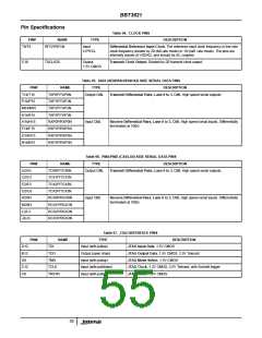
Table 100. I C 2-WIRE SERIAL DATA INTERFACE PINS
PIN#
NAME
TYPE
I/O (open drain)
I/O (open drain)
Input
DESCRIPTION
2
P9
P8
C7
SDA
I C Serial Address/Data I/O 1.5V CMOS, 2.5V Tolerant and Compatible
2
SCL
I C Serial Interface Clock. 1.5V CMOS, 2.5V Tolerant and Compatible
2
WRTP
I C Serial Interface Write Protection. When high, no write to protected
XENPAK basic NVR area is allowed. 1.5V CMOS, 2.5V Tolerant
R6
P7
N7
N6
P6
GPIO[4]
GPIO[3]
GPIO[2]
GPIO[1]
GPIO[0]
I/O (open drain)
General Purpose I/O Can be used for optical monitoring and status
reporting, and to trigger LASI, or for external control functions. 1.5V CMOS,
2.5V Tolerant and Compatible
Table 101. VOLTAGE SUPPLY PINS
TYPE
PIN#
C6, C13, H13, J4, N5, N13
NAME
VDDPR
DESCRIPTION
Supply
2.5V Protection Voltage Supply. May be same level as VDD if no inputs
or outputs go above the VDD level.
A4, A8, A9, A12, A13, B10, N9, VDD
P4, P5
Supply
1.5V Digital and Core Supply
B4, C4, C14, D4, D13, E4, E13, VDDA
F4, F13, G4, G13, K4, K13, L4,
L13, M4, M13, N4, P13, R4, R13,
T4, T13
Analog Supply
1.5V Analog Supply. Should be decoupled from VDD
R7, T7
VDDAV
VDDAC
Analog Supply
Analog Supply
Ground
Analog supply for VCO. Should be decoupled from VDDA
Analog supply for CMU. Should be decoupled from VDDA
R10, T10
A1, A14, A15, A16, B1, B2, B3, GNDA
B8, B13, B16, C1, C9, C11, C15,
C16, D1, D2, D3, D16, E1, E14,
E15, E16, F1, F2, F3, F16, G1,
G14, G15, G16, H1, H2, H3, H4,
H16, J1, J13, J14, J15, J16, K1,
K2, K3, K16, L1, L14, L15, L16,
M1, M2, M3, M16, N1, N14, N15,
N16, P1, P2, P3, P16, R1, R8,
R9, R14, R15, R16, T1, T2, T3,
T6, T16
Ground. Electrically well grounded. Analog and Digital grounds are tied in
the device, but it is recommended that some separation be provided in the
PCB planes outside the device, to minimize the coupling between digital
signals and the analog sections of the device.
57

 INTERSIL [ Intersil ]