BBT3821
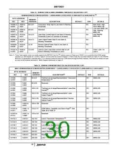
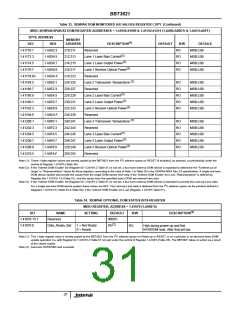
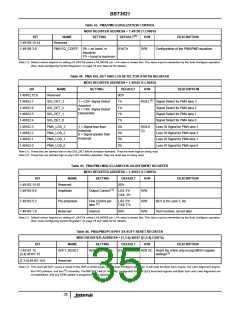
Table 33. XENPAK DOM MONITORED A/D VALUES REGISTER COPY (Continued)
MDIO XENPAK/XPAK/X2 DOM REGISTER ADDRESSES = 1.41056:41069 & 1.41152:41215 (1.A060:A06D’h & 1.A0C0:A0FF)
BYTE ADDRESS
MEMORY
(1)
DEC
1.41170:1
1.41172:3
1.41174:5
1.41176:7
1.41178:83
1.41184:5
1.41186:7
1.41188:9
1.41190:1
1.41192:3
1.41194:9
1.41200:1
1.41202:3
1.41204:5
1.41206:7
1.41208:9
1.41210:5
HEX
1.A0D2:3
1.A0D4:5
1.A0D6:7
1.A0D8:9
1.A0DA:F
1.A0E0:1
1.A0E2:3
1.A0E4:5
1.A0E6:7
1.A0E8:9
1.A0EA:F
1.A0F0:1
1.A0F2:3
1.A0F4:5
1.A0F6:7
1.A0F8:9
1.A0FA:F
ADDRESS
210:211
212:213
214:215
216:217
218:223
224:225
226:227
228:229
230:231
232:233
234:239
240:241
242:243
244:245
246:247
228:249
250:255
DESCRIPTION
DEFAULT
R/W
RO
DETAILS
MSB:LSB
Reserved
(3)
Lane 1 Laser Bias Current
Lane 1 Laser Output Power
RO
RO
RO
MSB:LSB
MSB:LSB
MSB:LSB
(3)
(3)
Lane 1 Receive Optical Power
Reserved
(3)
Lane 2 Transceiver Temperature
Reserved
RO
RO
RO
RO
RO
MSB:LSB
MSB:LSB
MSB:LSB
MSB:LSB
MSB:LSB
(3)
Lane 2 Laser Bias Current
(3)
Lane 2 Laser Output Power
(3)
Lane 2 Receive Optical Power
Reserved
(3)
Lane 3 Transceiver Temperature
Reserved
RO
RO
RO
RO
RO
MSB:LSB
MSB:LSB
MSB:LSB
MSB:LSB
MSB:LSB
(3)
Lane 3 Laser Bias Current
(3)
Lane 3 Laser Output Power
(3)
Lane 3 Receive Optical Power
Reserved
2
Note (1): These 1-byte register values are merely copied by the BBT3821 from the I C address space on RESET (if enabled), on demand, or periodically under the
control of Register 1.A100’h (Table 38).
Note (2): If the ‘Indirect DOM Enable’ bit (Register bit 1.C018’h.2 Table 51) is not set, a four-lane external DOM device is expected to determine the “Farthest out of
range” or “Representative” values for these registers, according to the rules of Note 1 to Table 28 in the XENPAK MSA Rev 3.0 specification. A single one-lane
DOM device system will provide the values from the single DOM device here only. If the ‘Indirect DOM Enable’ bit is set, “Representative” is defined by
Register bits 1.C018’h.1:0 (Table 51), and the values from the specified lane’s DOM are entered here also.
Note (3): If the ‘Indirect DOM Enable’ bit (Register bit 1.C018’h.2 Table 51) is not set, a four-lane external DOM device is expected to provide the Lane-by-Lane data.
2
For a single one-lane DOM device system these values are 00’h. The Lane-by-Lane data is obtained from the I C address space via the pointers defined in
Registers 1.C019:C’h (Table 53 & Table 54), if the ‘Indirect DOM Enable’ bit is set (Register 1.C018’h Table 51).
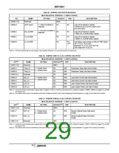
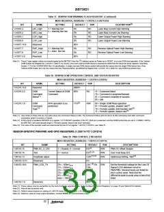
Table 34. XENPAK OPTIONAL DOM STATUS BITS REGISTER
MDIO REGISTER, ADDRESS = 1.41070 (1.A06E’h)
(1)
BIT
1.41070.15:1
1.41070.0
NAME
Reserved
Data_Ready_Bar
SETTING
DEFAULT
R/W
DESCRIPTION
0000’h
(2)
1 = Not Ready
0 = Ready
0’b
RO
High during power-up and first
NVR/DOM read. After that set low.
2
Note (1): This 1-byte register value is merely copied by the BBT3821 from the I C address space on Power-up or RESET, or on a periodic or on-demand direct DOM
update operation (i.e. with Register bit 1.C018’h.2 Table 51 not set) under the control of Register 1.A100’h (Table 38). The BBT3821 takes no action as a result
of the values copied.
Note (2): Assumes NVR/DOM read succeeds
31

 INTERSIL [ Intersil ]