BBT3821
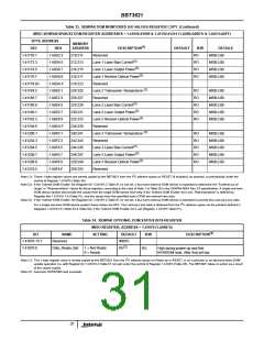
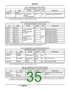
Table 43. PMA/PMD EQUALIZATION CONTROL
MDIO REGISTER ADDRESS = 1.49158 (1.C006’h)
(1)
BIT
1.49158.15:14
1.49158.3:0
NAME
Reserved
SETTING
DEFAULT
R/W
DESCRIPTION
PMA EQ_COEFF 0’h = no boost in
equalizer.
0’h/C’h
R/W
Configuration of the PMA/PMD equalizer
F’h = boost is maximum
Note (1): Default values depend on setting of LX4/CX4 select LX4_MODE pin. LX4 value is shown first. The value may be overwritten by the Auto-Configure operation
(See “Auto-Configuring Control Registers” on page 16 and Table 92 for details).
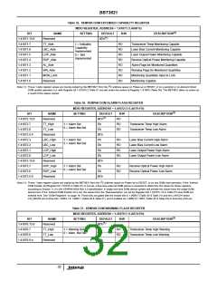
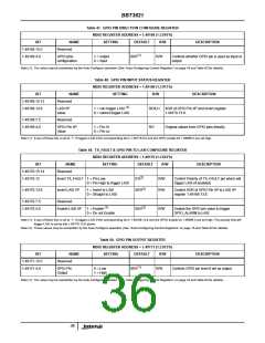
Table 44. PMA SIG_DET AND LOS DETECTOR STATUS REGISTER
MDIO REGISTER ADDRESS = 1.49162 (1.C00A’h)
BIT
1.49162.15:8
1.49162.7
1.49162.6
1.49162.5
1.49162.4
1.49162.3
1.49162.2
1.49162.1
1.49162.0
NAME
Reserved
SETTING
DEFAULT
00’b
R/W
DESCRIPTION
(1)
SIG_DET_3
SIG_DET_2
SIG_DET_1
SIG_DET_0
PMA_LOS_3
PMA_LOS_2
PMA_LOS_1
PMA_LOS_0
1 = CX4 Signal Detect
Asserted
0 = CX4 Signal Detect
Deasserted
1’b
1’b
1’b
1’b
0’b
0’b
0’b
0’b
RO/LL
Signal Detect for PMA lane 3
Signal Detect for PMA lane 2
Signal Detect for PMA lane 1
Signal Detect for PMA lane 0
Loss Of Signal for PMA lane 3
Loss Of Signal for PMA lane 2
Loss Of Signal for PMA lane 1
Loss Of Signal for PMA lane 0
1 = Signal less than
threshold
0 = Signal greater than
threshold
RO/LH
(2)
Note (1): These bits are latched low on any SIG_DET failure condition detected. They are reset high on being read.
Note (2): These bits are latched high on any LOS condition detected. They are reset low on being read.
Table 45. PMA/PMD MISCELLANEOUS ADJUSTMENT REGISTER
MDIO REGISTER ADDRESS = 1.49163 (1.C00B’h)
BIT
1.49163.15:10
1.49163.9:6
NAME
Reserved
SETTING
DEFAULT
00’h
R/W
DESCRIPTION
(1)
Amplitude
Output Control
LX4: 5’h
CX4: 3’h
R/W
1.49163.5:2
1.49163.1:0
Pre-emphasis
Reserved
Fine Control per
LX4: 0’h
CX4: F’h
R/W
R/W
Bit 5 is for Lane 3, etc.
Test Function, do not alter.
(1)
lane
Internal
00’b
Note (1): Default values depend on setting of LX4/CX4 select LX4_MODE pin. LX4 value is shown first. The value may be overwritten by the Auto-Configure operation
(See “Auto-Configuring Control Registers” on page 16 and Table 92 for details).
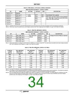
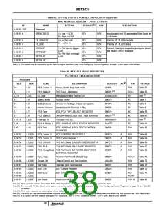
Table 46. PMA/PMD/PCS/PHY XS SOFT RESET REGISTER
MDIO REGISTER ADDRESS = [1,3:4].49167 ([1,3:4].C00F’h)
BIT
NAME
SETTING
DEFAULT
0’b
R/W
DESCRIPTION
1.49167.15
[3,4].49167.15
SOFT_RESET
Write 1 to initiate.
R/W SC Reset the entire chip except MDIO register
(1)
settings
[1,3:4].49167.14:0
Reserved
Note (1): This reset will NOT cause a reload of the NVR or DOM areas, nor an Auto-Configure operation. It will reset the Byte Sync engine, the Lane Alignment engine,
2
the FIFO pointers, and the I C controller. The BBT3821 will (if “normally” configured) transmit ||LF|| local fault signals until Byte Sync and Lane Alignment are
re-established, and any DOM update in progress may be aborted.
35

 INTERSIL [ Intersil ]