LXT971A 3.3V Dual-Speed Fast Ethernet Transceiver
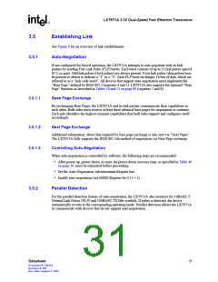
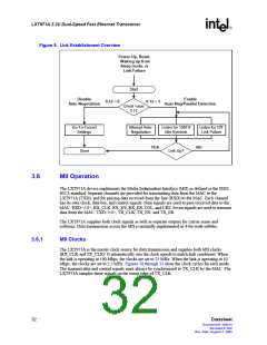
Figure 9. Link Establishment Overview
Power-Up, Reset,
Waking up from
Sleep mode, or
Link Failure
Start
Disable
Enable
0.12 = 0
0.12 = 1
Auto-Negotiation
Auto-Neg/Parallel Detection
Check Value
0.12
Go To Forced
Settings
Attempt Auto-
Negotiation
Listen for 100TX
Idle Symbols
Listen for 10T
Link Pulses
YES
NO
Done
Link Up?
3.6
MII Operation
The LXT971A device implements the Media Independent Interface (MII) as defined in the IEEE
802.3 standard. Separate channels are provided for transmitting data from the MAC to the
LXT971A (TXD), and for passing data received from the line (RXD) to the MAC. Each channel
has its own clock, data bus, and control signals. Nine signals are used to pass received data to the
MAC: RXD<3:0>, RX_CLK, RX_DV, RX_ER, COL, and CRS. Seven signals are used to transmit
data from the MAC: TXD<3:0>, TX_CLK, TX_EN, and TX_ER.
The LXT971A supplies both clock signals as well as separate outputs for carrier sense and
collision. Data transmission across the MII is normally implemented in 4-bit-wide nibbles.
3.6.1
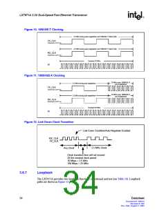
MII Clocks
The LXT971A is the master clock source for data transmission and supplies both MII clocks
(RX_CLK and TX_CLK). It automatically sets the clock speeds to match link conditions. When
the link is operating at 100 Mbps, the clocks are set to 25 MHz. When the link is operating at 10
Mbps, the clocks are set to 2.5 MHz. Figures 10 through 12 show the clock cycles for each mode.
The transmit data and control signals must always be synchronized to TX_CLK by the MAC. The
LXT971A samples these signals on the rising edge of TX_CLK.
32
Datasheet
Document #: 249414
Revision #: 002
Rev. Date: August 7, 2002

 INTEL [ INTEL ]