LXT971A 3.3V Dual-Speed Fast Ethernet Transceiver
3.4.5
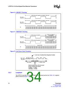
Hardware Configuration Settings
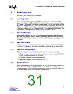
The LXT971A provides a hardware option to set the initial device configuration. The hardware
option uses the three LED driver pins. This provides three control bits, as listed in Table 9. The
LED drivers can operate as either open-drain or open-source circuits as shown in Figure 8.
Figure 8. Hardware Configuration Settings
3.3 V
Configuration Bit = 1
Configuration Bit = 0
LED/CFG Pin
LED/CFG Pin
1. The LED/CFG pins automatically adjust their
polarity upon power-up or reset.
2. Unused LEDs may be implemented with pull-up/
pull-down resistors of 10 K.
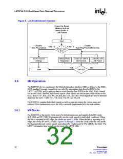
Table 9. Hardware Configuration Settings
Resulting Register Bit Values
LED/CFGn
Desired Mode
Pin Settings1
Control Register
AN Advertisement Registers
Auto-
Auto-
Speed
(Mbps)
Speed
0.13
FD
0.8
100FD 100TX 10FD 10T
Duplex
1
2
3
Neg
0.12
Neg
4.8
4.7
4.6
4.5
Half
Full
Half
Full
Half
Full
Low Low Low
Low Low High
Low High Low
Low High High
High Low Low
High Low High
0
1
0
1
0
1
10
0
1
N/A
Disabled
0
1
Auto-Negotiation Adver-
tisement
100
0
1
1
1
0
0
0
0
100
Only
Half
Enabled
1
High High Low
High High High
0
1
0
1
1
1
0
1
1
1
Only
10/100
Full or
Half
1. Refer to Table 7 on page 19 for LED/CFG pin assignments.
30
Datasheet
Document #: 249414
Revision #: 002
Rev. Date: August 7, 2002

 INTEL [ INTEL ]