LXT971A 3.3V Dual-Speed Fast Ethernet Transceiver
3.4.3.2
3.4.3.3
Software Power Down
Software power-down control is provided by Register bit 0.11 in the Control Register (refer to
Table 43 on page 74). During soft power-down, the following conditions are true:
• The network port is shut down.
• The MDIO registers remain accessible.
Sleep Mode
The LXT971A supports a power-saving sleep mode. Sleep mode is enabled when SLEEP is
asserted via pin 32(LQFP)/H7(PBGA). The value of pin 32/H7 can be overridden by Register bit
16.6 when in managed mode as shown in Table 4 on page 18. The LXT971A enters into sleep
mode when SLEEP is enabled and no energy is detected on the twisted-pair input for 1-3 seconds
(the time is controlled by Register bits 16.4:3 in the Configuration Register, with a default of 3.04
seconds).
During this mode, the LXT971A still responds to management transactions (MDC/MDIO). In this
mode the power consumption is minimized, and the supply current is reduced below the maximum
value given in Table 18 on page 56. If the LXT971A detects activity on the twisted-pair inputs, it
comes out of the sleep state and check for link. If no link is detected in 1-3 seconds
(programmable) it reverts back to the low power sleep state.
Note: Sleep Mode is not functional in fiber network applications.
3.4.4
Reset
The LXT971A provides both hardware and software resets. Configuration control of auto-
negotiation, speed, and duplex mode selection is handled differently for each. During a hardware
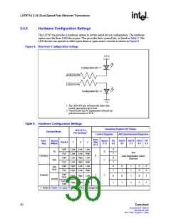
reset, auto-negotiation and speed configuration settings are read in from pins (refer to Table 9 on
page 30 for pin settings and to Table 43 on page 74 for register bit definitions).
During a software reset (0.15 = 1), these bit settings are not re-read from the pins. They revert back
to the values that were read in during the last hardware reset. Therefore, any changes to pin values
made since the last hardware reset is not detected during a software reset.
During a hardware reset, register information is unavailable for 1 ms after de-assertion of the reset.
During a software reset (0.15 = 1) the registers are available for reading. The reset bit should be
polled to see when the part has completed reset (0.15 = 0).
Datasheet
29
Document #: 249414
Revision #: 002
Rev. Date: August 7, 2002

 INTEL [ INTEL ]