LXT971A 3.3V Dual-Speed Fast Ethernet Transceiver
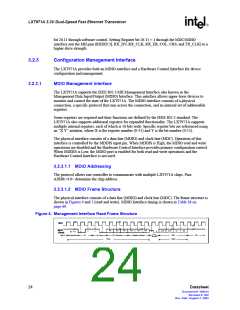
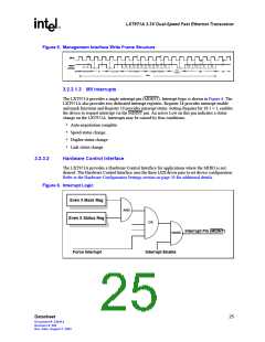
Figure 5. Management Interface Write Frame Structure
MDC
MDIO
A4
A3
A0
R4
R3
R0
D15
D14
D1
D0
32 "1"s
0
1
0
1
0
1
(Write)
Turn
Around
Idle
Preamble
ST
Op Code
PHY Address
Register Address
Data
Idle
Write
3.2.3.1.3 MII Interrupts
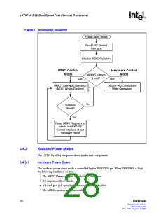
The LXT971A provides a single interrupt pin (MDINT). Interrupt logic is shown in Figure 6. The
LXT971A also provides two dedicated interrupt registers. Register 18 provides interrupt enable
and mask functions and Register 19 provides interrupt status. Setting Register bit 18.1 = 1, enables
the device to request interrupt via the MDINT pin. An active Low on this pin indicates a status
change on the LXT971A. Interrupts may be caused by four conditions:
• Auto-negotiation complete
• Speed status change
• Duplex status change
• Link status change
3.2.3.2
Hardware Control Interface
The LXT971A provides a Hardware Control Interface for applications where the MDIO is not
desired. The Hardware Control Interface uses the three LED driver pins to set device configuration.
Refer to the Hardware Configuration Settings section on page 30 for additional details.
Figure 6. Interrupt Logic
Even X Mask Reg
Even X Status Reg
AND
OR
Interrupt Pin (MDINT)
NAND
Force Interrupt
Interrupt Enable
Datasheet
25
Document #: 249414
Revision #: 002
Rev. Date: August 7, 2002

 INTEL [ INTEL ]