®
MOBILE PENTIUM PROCESSOR WITH MMX™ TECHNOLOGY
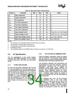
Table 14. Input and Output Characteristics
Symbol
CIN
Parameter
Min
Max
15
Unit
pF
pF
pF
pF
pF
pF
pF
mA
mA
mA
mA
Notes
Input Capacitance
4
4
4
4
4
4
4
CO
Output Capacitance
20
CI/O
CCLK
CTIN
CTOUT
CTCK
ILI
I/O Capacitance
25
CLK Input Capacitance
Test Input Capacitance
Test Output Capacitance
Test Clock Capacitance
Input Leakage Current
Output Leakage Current
Input High Leakage Current
Input Low Leakage Current
15
15
20
15
±15
±15
200
- 400
0<VIN <VIL, VIH < VIN <VCC3(1)
0<VIN <VIL, VIH < VIN <VCC3(1)
VIN = VCC3 - 0.4V (3)
ILO
IIH
IIL
VIN = 0.4V (2,5)
NOTES:
1.
2.
3.
4.
5.
This parameter is for inputs/outputs without an internal pull up or pull down.
This parameter is for inputs with an internal pull up.
This parameter is for inputs with an internal pull down.
Guaranteed by design.
This specification applies to the HITM# pin when it is driven as an input (e.g., in JTAG mode).
4.3.2.
DECOUPLING RECOMMENDATIONS
4.3.
AC Specifications
Liberal decoupling capacitance should be placed
near the processor. The processor’s large address
and data buses can cause transient power surges,
particularly when driving large capacitive loads.
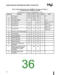
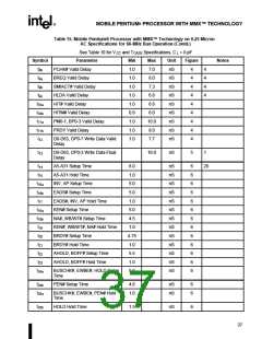
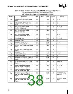
The AC specifications of the mobile Pentium
processor with MMX technology on 0.25 Micron
consist of setup times, hold times, and valid delays
at 0 pF.
Low inductance capacitors and interconnects are
recommended for best high frequency electrical
performance. Inductance can be reduced by
shortening circuit board traces between the
processor and decoupling capacitors as much as
possible. These capacitors should be evenly
distributed around each component on the power
plane. Capacitor values should be chosen to
ensure they eliminate both low and high frequency
noise components.
4.3.1.
POWER AND GROUND
For clean on-chip power distribution, the TCP has
37 VCC2 (core power), 42 VCC3 (I/O power) and 72
VSS (ground) inputs. Power and ground connections
must be made to all external VCC2, VCC3 and VSS
pins. On the circuit board all VCC2 pins must be
connected to a 1.8V (166/200/233 MHz) or 2.0V
(266 MHz) VCC2 plane (or island) and all VCC3 pins
must be connected to a 2.5V VCC3 plane. All VSS
pins must be connected to a VSS plane. Please
refer to Table 2 for the list of VCC2, VCC3 and VSS
pins.
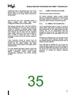
Power transients also occur as the processor
rapidly transitions from
a
low level power
consumption to a high level one (or high to low
power transition). A typical example would be
entering or exiting the Stop Grant state. Another
example would be executing a HALT instruction,
causing the processor to enter the Auto HALT
34

 INTEL [ INTEL ]