Processor Configuration Registers
2.6.43
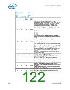
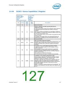
SLOTSTS—Slot Status Register
This is a PCI Express* Slot related register.
B/D/F/Type:
Address Offset:
Reset Value:
Access:
0/1/0–2/PCI
BA–BBh
0000h
RO, RW1C, RO-V
16 bits
Size:
BIOS Optimal Default
00h
Reset
Value
RST/
PWR
Bit
Access
Description
15:9
RO
0h
Reserved (RSVD)
Reserved for Data Link Layer State Changed (DLLSC)
This bit is set when the value reported in the Data Link Layer Link
Active field of the Link Status register is changed. In response to
a Data Link Layer State Changed event, software must read the
Data Link Layer Link Active field of the Link Status register to
determine if the link is active before initiating configuration cycles
to the hot plugged device.
8
7
RO
RO
0b
Uncore
Uncore
Reserved for Electromechanical Interlock Status (EIS)
If an Electromechanical Interlock is implemented, this bit
indicates the current status of the Electromechanical Interlock.
0b
0 = Electromechanical Interlock Disengaged
1 = Electromechanical Interlock Engaged
Presence Detect State (PDS)
In band presence detect state:
0 = Slot Empty
1 = Card present in slot
This bit indicates the presence of an adapter in the slot, reflected
by the logical "OR" of the Physical Layer in-band presence detect
mechanism and, if present, any out-of-band presence detect
mechanism defined for the slot's corresponding form factor. Note
that the in-band presence detect mechanism requires that power
be applied to an adapter for its presence to be detected.
Consequently, form factors that require a power controller for
hot-plug must implement a physical pin presence detect
mechanism.
6
RO-V
0b
Uncore
0 = Slot Empty
1 = Card Present in slot
This register must be implemented on all Downstream Ports that
implement slots. For Downstream Ports not connected to slots
(where the Slot Implemented bit of the PCI Express Capabilities
Register is 0b), this bit must return 1b.
Reserved for MRL Sensor State (MSS)
This register reports the status of the MRL sensor if it is
implemented.
5
RO
0b
Uncore
0 = MRL Closed
1 = MRL Open
Reserved for Command Completed (CC)
If Command Completed notification is supported (as indicated by
No Command Completed Support field of Slot Capabilities
Register), this bit is set when a hot-plug command has completed
and the Hot-Plug Controller is ready to accept a subsequent
command. The Command Completed status bit is set as an
indication to host software that the Hot-Plug Controller has
processed the previous command and is ready to receive the
next command; it provides no assurance that the action
corresponding to the command is complete.
4
RO
0b
Uncore
If Command Completed notification is not supported, this bit
must be hardwired to 0b.
Datasheet, Volume 2
123

 INTEL [ INTEL ]