LPC Interface Bridge Registers (D31:F0)
13.6.2.3
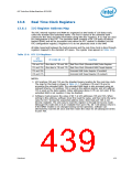
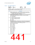
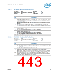
RTC_REGC—Register C (Flag Register)
RTC Index:
Default Value:
Lockable:
0Ch
00U00000 (U: Undefined) Size:
No Power Well:
Attribute:
RO
8-bit
RTC
Writes to Register C have no effect.
Bit
Description
Interrupt Request Flag (IRQF) — RO. IRQF = (PF * PIE) + (AF * AIE) + (UF *UFE).
This bit also causes the RTC Interrupt to be asserted. This bit is cleared upon RSMRST#
or a read of Register C.
7
6
5
Periodic Interrupt Flag (PF) — RO. This bit is cleared upon RSMRST# or a read of
Register C.
0 = If no taps are specified via the RS bits in Register A, this flag will not be set.
1 = Periodic interrupt Flag will be 1 when the tap specified by the RS bits of register A is
1.
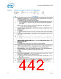
Alarm Flag (AF) — RO.
0 = This bit is cleared upon RTCRST# or a read of Register C.
1 = Alarm Flag will be set after all Alarm values match the current time.
Update-Ended Flag (UF) — RO.
4
0 = The bit is cleared upon RSMRST# or a read of Register C.
1 = Set immediately following an update cycle for each second.
3:0
Reserved. Will always report 0.
13.6.2.4
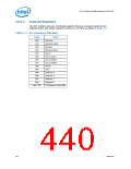
RTC_REGD—Register D (Flag Register)
RTC Index:
Default Value:
Lockable:
0Dh
10UUUUUU (U: Undefined) Size:
No Power Well:
Attribute:
R/W
8-bit
RTC
Bit
Description
Valid RAM and Time Bit (VRT) — R/W.
0 = This bit should always be written as a 0 for write cycle, however it will return a 1 for
read cycles.
1 = This bit is hardwired to 1 in the RTC power well.
7
6
Reserved. This bit always returns a 0 and should be set to 0 for write cycles.
Date Alarm — R/W. These bits store the date of month alarm value. If set to 000000b,
then a don’t care state is assumed. The host must configure the date alarm for these
bits to do anything, yet they can be written at any time. If the date alarm is not
enabled, these bits will return 0s to mimic the functionality of the Motorola 146818B.
These bits are not affected by any reset assertion.
5:0
Datasheet
443

 INTEL [ INTEL ]