LPC Interface Bridge Registers (D31:F0)
13.5.7
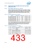
REDIR_TBL—Redirection Table (LPC I/F—D31:F0)
Index Offset:
Default Value:
10h–11h (vector 0) throughAttribute:R/W, RO
3E–3Fh (vector 23)
Bit 16 = 1. All other bits undefinedSize:64 bits each, (accessed as two
32 bit quantities)
The Redirection Table has a dedicated entry for each interrupt input pin. The
information in the Redirection Table is used to translate the interrupt manifestation on
the corresponding interrupt pin into an APIC message.
The APIC will respond to an edge triggered interrupt as long as the interrupt is held
until after the acknowledge cycle has begun. Once the interrupt is detected, a delivery
status bit internally to the I/O APIC is set. The state machine will step ahead and wait
for an acknowledgment from the APIC unit that the interrupt message was sent. Only
then will the I/O APIC be able to recognize a new edge on that interrupt pin. That new
edge will only result in a new invocation of the handler if its acceptance by the
destination APIC causes the Interrupt Request Register bit to go from 0 to 1.
(In other words, if the interrupt was not already pending at the destination.)
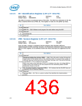
Bit
Description
Destination — R/W. If bit 11 of this entry is 0 (Physical), then bits 59:56 specifies an
APIC ID. In this case, bits 63:59 should be programmed by software to 0.
If bit 11 of this entry is 1 (Logical), then bits 63:56 specify the logical destination
address of a set of processors.
63:56
Extended Destination ID (EDID) — RO. These bits are sent to a local APIC only
when in Processor System Bus mode. They become bits 11:4 of the address.
55:48
47:17 Reserved
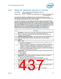
Mask — R/W.
0 = Not masked: An edge or level on this interrupt pin results in the delivery of the
interrupt to the destination.
1 = Masked: Interrupts are not delivered nor held pending. Setting this bit after the
interrupt is accepted by a local APIC has no effect on that interrupt. This behavior
is identical to the device withdrawing the interrupt before it is posted to the
processor. It is software's responsibility to deal with the case where the mask bit is
set after the interrupt message has been accepted by a local APIC unit but before
the interrupt is dispensed to the processor.
16
Trigger Mode — R/W. This field indicates the type of signal on the interrupt pin that
triggers an interrupt.
15
14
13
12
0 = Edge triggered.
1 = Level triggered.
Remote IRR — R/W. This bit is used for level triggered interrupts; its meaning is
undefined for edge triggered interrupts.
0 = Reset when an EOI message is received from a local APIC.
1 = Set when Local APIC/s accept the level interrupt sent by the I/O APIC.
Interrupt Input Pin Polarity — R/W. This bit specifies the polarity of each interrupt
signal connected to the interrupt pins.
0 = Active high.
1 = Active low.
Delivery Status — RO. This field contains the current status of the delivery of this
interrupt. Writes to this bit have no effect.
0 = Idle. No activity for this interrupt.
1 = Pending. Interrupt has been injected, but delivery is not complete.
Datasheet
437

 INTEL [ INTEL ]