LPC Interface Bridge Registers (D31:F0)
13.5
Advanced Programmable Interrupt Controller
(APIC)(D31:F0)
13.5.1
APIC Register Map (LPC I/F—D31:F0)
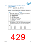
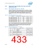
The APIC is accessed via an indirect addressing scheme. Two registers are visible by
software for manipulation of most of the APIC registers. These registers are mapped
into memory space. The address bits 15:12 (Consumer Only) and 19:12 (Corporate
Only) of the address range are programmable through bits 7:4 (Consumer Only) and
7:0 (Corporate Only) of OIC register (Chipset Config Registers:Offset 31FFh for
Consumer Family and Offset 31FEh for Corporate family) The registers are shown in
Table 13-4.
Table 13-4. APIC Direct Registers (LPC I/F—D31:F0)
Address
Mnemonic
Register Name
Size
Type
FEC_ _0000h (Corporate Only)
FEC0_0000h (Consumer Only)
FEC_ _0010h (Corporate Only)
FEC0_0010h (Consumer Only)
FEC_ _0040h (Corporate Only)
FECO_0040h (Consumer Only)
IND
IND
Index
Index
Data
Data
EOI
8 bits
8 bits
R/W
R/W
R/W
R/W
WO
DAT
DAT
EOIR
EOIR
32 bits
32 bits
32 bits
32 bits
EOI
WO
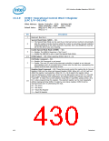
Table 13-5 lists the registers which can be accessed within the APIC via the Index
Register. When accessing these registers, accesses must be done one dword at a time.
For example, software should never access byte 2 from the Data register before
accessing bytes 0 and 1. The hardware will not attempt to recover from a bad
programming model in this case.
Table 13-5. APIC Indirect Registers (LPC I/F—D31:F0)
Index
Mnemonic
Register Name
Identification
Size
Type
00
ID
32 bits
32 bits
—
R/W
RO
01
VER
—
Version
02–0F
10–11
12–13
...
Reserved
RO
REDIR_TBL0
REDIR_TBL1
...
Redirection Table 0
Redirection Table 1
...
64 bits
64 bits
...
R/W, RO
R/W, RO
...
3E–3F
40–FF
REDIR_TBL23 Redirection Table 23
Reserved
64 bits
—
R/W, RO
RO
—
Datasheet
433

 INTEL [ INTEL ]