LPC Interface Bridge Registers (D31:F0)
13.3.1
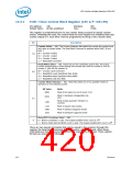
TCW—Timer Control Word Register (LPC I/F—D31:F0)
I/O Address:
Default Value:
43h
Attribute:
Size:
WO
8 bits
All bits undefined
This register is programmed prior to any counter being accessed to specify counter
modes. Following part reset, the control words for each register are undefined and each
counter output is 0. Each timer must be programmed to bring it into a known state.
Bit
Description
Counter Select — WO. The Counter Selection bits select the counter the control word
acts upon as shown below. The Read Back Command is selected when bits[7:6] are
both 1.
00 = Counter 0 select
01 = Counter 1 select
10 = Counter 2 select
11 = Read Back Command
7:6
Read/Write Select — WO. These bits are the read/write control bits. The actual
counter programming is done through the counter port (40h for counter 0, 41h for
counter 1, and 42h for counter 2).
00 = Counter Latch Command
5:4
01 = Read/Write Least Significant Byte (LSB)
10 = Read/Write Most Significant Byte (MSB)
11 = Read/Write LSB then MSB
Counter Mode Selection — WO. These bits select one of six possible modes of
operation for the selected counter.
Bit Value
Mode
000b
Mode 0 Out signal on end of count (=0)
Mode 1 Hardware retriggerable one-
shot
001b
x10b
3:1
Mode 2 Rate generator (divide by n
counter)
x11b
100b
101b
Mode 3 Square wave output
Mode 4 Software triggered strobe
Mode 5 Hardware triggered strobe
Binary/BCD Countdown Select — WO.
16
0
0 = Binary countdown is used. The largest possible binary count is 2
4
1 = Binary coded decimal (BCD) count is used. The largest possible BCD count is 10
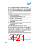
There are two special commands that can be issued to the counters through this
register, the Read Back Command and the Counter Latch Command. When these
commands are chosen, several bits within this register are redefined. These register
formats are described as follows:
420
Datasheet

 INTEL [ INTEL ]