Functional Description
5.7.1
Timer Programming
The counter/timers are programmed in the following fashion:
1. Write a control word to select a counter.
2. Write an initial count for that counter.
3. Load the least and/or most significant bytes (as required by Control Word bits 5, 4)
of the 16-bit counter.
4. Repeat with other counters.
Only two conventions need to be observed when programming the counters. First, for
each counter, the control word must be written before the initial count is written.
Second, the initial count must follow the count format specified in the control word
(least significant byte only, most significant byte only, or least significant byte and then
most significant byte).
A new initial count may be written to a counter at any time without affecting the
counter's programmed mode. Counting is affected as described in the mode definitions.
The new count must follow the programmed count format.
If a counter is programmed to read/write two-byte counts, the following precaution
applies: A program must not transfer control between writing the first and second byte
to another routine which also writes into that same counter. Otherwise, the counter will
be loaded with an incorrect count.
The Control Word Register at port 43h controls the operation of all three counters.
Several commands are available:
• Control Word Command. Specifies which counter to read or write, the operating
mode, and the count format (binary or BCD).
• Counter Latch Command. Latches the current count so that it can be read by the
system. The countdown process continues.
• Read Back Command. Reads the count value, programmed mode, the current
state of the OUT pins, and the state of the Null Count Flag of the selected counter.
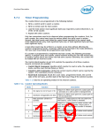
Table 5-12 lists the six operating modes for the interval counters.
Table 5-12. Counter Operating Modes
Mode
Function
Description
Output is 0. When count goes to 0, output goes to
1 and stays at 1 until counter is reprogrammed.
0
Out signal on end of count (=0)
Output is 0. When count goes to 0, output goes to
1 for one clock time.
1
2
Hardware retriggerable one-shot
Rate generator (divide by n
counter)
Output is 1. Output goes to 0 for one clock time,
then back to 1 and counter is reloaded.
Output is 1. Output goes to 0 when counter rolls
over, and counter is reloaded. Output goes to 1
when counter rolls over, and counter is reloaded,
etc.
3
Square wave output
Output is 1. Output goes to 0 when count expires
for one clock time.
4
5
Software triggered strobe
Hardware triggered strobe
Output is 1. Output goes to 0 when count expires
for one clock time.
Datasheet
119

 INTEL [ INTEL ]