Functional Description
Interrupts can individually be programmed to be edge or level, except for IRQ0, IRQ2,
IRQ8#, and IRQ13.
Note:
Active-low interrupt sources (e.g., the PIRQ#s) are inverted inside the ICH10. In the
following descriptions of the 8259s, the interrupt levels are in reference to the signals
at the internal interface of the 8259s, after the required inversions have occurred.
Therefore, the term “high” indicates “active,” which means “low” on an originating
PIRQ#.
5.8.1
Interrupt Handling
5.8.1.1
Generating Interrupts
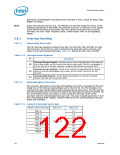
The PIC interrupt sequence involves three bits, from the IRR, ISR, and IMR, for each
interrupt level. These bits are used to determine the interrupt vector returned, and
status of any other pending interrupts. Table 5-14 defines the IRR, ISR, and IMR.
Table 5-14. Interrupt Status Registers
Bit
Description
Interrupt Request Register. This bit is set on a low to high transition of the interrupt
line in edge mode, and by an active high level in level mode. This bit is set whether or
not the interrupt is masked. However, a masked interrupt will not generate INTR.
IRR
Interrupt Service Register. This bit is set, and the corresponding IRR bit cleared,
when an interrupt acknowledge cycle is seen, and the vector returned is for that
interrupt.
ISR
IMR
Interrupt Mask Register. This bit determines whether an interrupt is masked.
Masked interrupts will not generate INTR.
5.8.1.2
Acknowledging Interrupts
The processor generates an interrupt acknowledge cycle that is translated by the host
bridge into a PCI Interrupt Acknowledge Cycle to the ICH10. The PIC translates this
command into two internal INTA# pulses expected by the 8259 cores. The PIC uses the
first internal INTA# pulse to freeze the state of the interrupts for priority resolution. On
the second INTA# pulse, the master or slave sends the interrupt vector to the
processor with the acknowledged interrupt code. This code is based upon bits [7:3] of
the corresponding ICW2 register, combined with three bits representing the interrupt
within that controller.
Table 5-15. Content of Interrupt Vector Byte
Master, Slave Interrupt
Bits [7:3]
Bits [2:0]
IRQ7,15
IRQ6,14
IRQ5,13
IRQ4,12
IRQ3,11
IRQ2,10
IRQ1,9
111
110
101
100
011
010
001
000
ICW2[7:3]
IRQ0,8
122
Datasheet

 INTEL [ INTEL ]