E
INTEL StrataFlash™ MEMORY TECHNOLOGY, 32 AND 64 MBIT
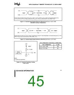
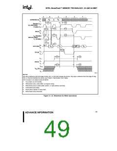
0606_17
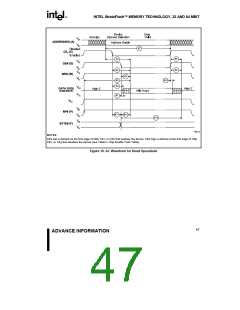
NOTES:
CEX low is defined as the first edge of CE , CE , or CE that enables the device. CEX high is defined at the first edge of CE ,
0
1
2
0
CE , or CE that disables the device (see Table 2, Chip Enable Truth Table).
1
2
STS is shown in its default mode (RY/BY#).
1. power-up and standby.
V
CC
2. Write block erase, write buffer, or program setup.
3. Write block erase or write buffer confirm, or valid address and data.
4. Automated erase delay.
5. Read status register or query data.
6. Write Read Array command.
Figure 17. AC Waveform for Write Operations
49
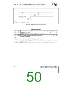
ADVANCE INFORMATION

 INTEL [ INTEL ]