Ultra-Low Voltage Intel® Celeron® Processor — 650 MHz and 400 MHz
5.0
Mechanical Specifications
5.1
Surface Mount Micro FC-BGA Package
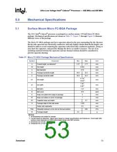
The ULV Intel® Celeron® processor is packaged in a surface mount, 479-ball Micro FC-BGA
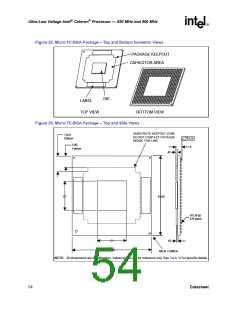
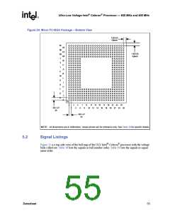
package. Mechanical specifications are shown in Table 37. Figure 22 through Figure 24 illustrate
different views of the package.
The Micro FC-BGA package may have capacitors placed in the area surrounding the die. Because
the die-side capacitors are electrically conductive, and only slightly shorter than the die height, care
should be taken to avoid contacting the capacitors with electrically conductive materials. Doing so
may short the capacitors, and possibly damage the device or render it inactive. The use of an
insulating material between the capacitors and any thermal solution should be considered to
prevent capacitor shorting.
Table 37. Micro FC-BGA Package Mechanical Specifications
Symbol
Parameter
Overall height, as delivered1
Min
Max
Unit
A
A2
b
2.27
2.77
mm
mm
mm
mm
mm
Die height
0.854
0.78
Ball diameter
D
Package substrate length
Package substrate width
34.9
34.9
35.1
35.1
E
3
11.18
10.82
D1
E1
Die length
Die width
mm
mm
4
3
7.20
6.85
4
e
Ball pitch
1.27
479
5
mm
each
mm
mm
mm
mm
mm
kPa
g
N
Ball count
K
K1
Keep-out outline from edge of package
Keep-out outline at corner of package
Capacitor keep-out height
Package edge to first ball center
Solder ball coplanarity
7
K2
-
0.7
S
1.625
0.2
--
Pdie
W
Allowable pressure on the die for thermal solution
Package weight
-
689
4.5
NOTES:
1. All dimensions are subject to change.
2. Overall height as delivered. Values were based on design specifications and tolerances. Final height after
surface mount depends on OEM motherboard design and SMT process.
3. Dimension for CPUID = 0x06B1.
4. Dimension for CPUID = 0x06B4.
Datasheet
53

 INTEL [ INTEL ]