LXT362 — Integrated T1 LH/SH Transceiver for DS1/DSX-1 or PRI Applications
4.0
Application Information
4.1
Transmit Return Loss
Table 18 shows the transmit return loss values for T1 applications. Table 24 on page 39 specifies
the receive return loss values.
4.2
4.3
Transformer Data
Specifications for transformers are listed in Table 19. A list of transformers recommended for use
with the LXT362 are specified in Table 20.
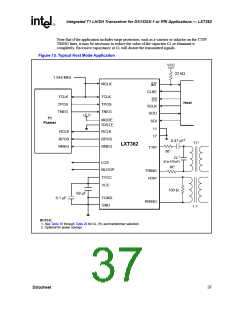
Application Circuits
Figure 12 and Figure 13 show typical LXT362 applications for Hardware and Host modes of
operation.
Table 18. Transmit Return Loss
Return Loss
(dB)
EC4:1
Xfrmr/Rt
1:2 / 9.1 Ω
1:1.151 / 0 Ω
1:22 / 0 Ω
RL (Ω)
100
CL (pF)
0
470
0
16
17
2
Refer to
Table 10
100
470
0
2
1
1001
100
(D4 Mode)
470
1
1. A 1:1.15 transmit transformer keeps the total transceiver power
dissipation at a low level, a 0.47 µF DC blocking capacitor must be
placed on TTIP or TRING.
2. A 0.47 µF DC blocking capacitor must be placed on TTIP or TRING.
Table 19. Transformer Specifications for LXT362
Leakage
Inductance
µH
Interwinding
Capacitance
pF
Dielectric
Breakdown
V
Primary
Inductance
µH (minimum)
DCR
Ω
(maximum)
Frequency
MHz
Turns
Ratio
Tx/Rx
(max)
(max)
(minimum)
0.90 pri, 1.70
sec
1
1.544
1.544
1.544
1:1.15
1:2
600
600
600
0.80
0.80
1.10
60
60
60
1500 VRMS
Tx
Rx
0.70 pri, 1.20
sec
1
1500 VRMS
1.10 pri, 1.10
sec
1
1:1
1500 VRMS
1. Some applications require transformers with a center tap (Long-Haul applications with DC current in the T1 loop).
34
Datasheet

 INTEL [ INTEL ]