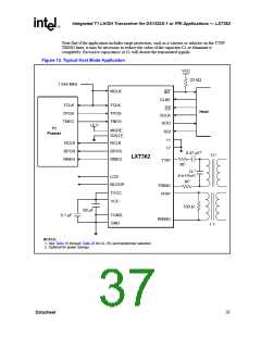
Integrated T1 LH/SH Transceiver for DS1/DSX-1 or PRI Applications — LXT362
Table 15. Performance Status Register Read Only, Address (A7-A0) = x010101x
Bit
Name
Function
1 = Loss of Signal occurred.
0
LOS
0 = Loss of Signal did not occur.
1 = Network loopback active.
1
2
NLOOP
AIS
0 = Network loopback not active.
1 = Alarm Indicator Signal detected.
0 = Alarm Indicator Signal not detected.
1 = Quasi-Random Signal Source pattern detected.
0 = Quasi-Random Signal Source pattern not detected.
3
4
5
QRSS
-
Reserved. Ignore.
1 = Driver Failure Monitor Open detected.
0 = Driver Failure Monitor Open not detected.
DFMO
1 = Built-In Self Test passed.
6
7
BIST
-
0 = Built-In Self Test did not pass (or was not run).
Reserved. Ignore.
Table 16. Equalizer Status Register Read Only, Address (A7-A0) = x010110x
Bit
Name
Function
0
1
2
3
4
5
6
7
-
Reserved. Ignore.
Reserved. Ignore.
Reserved. Ignore.
Reserved. Ignore.
-
-
-
LATN4
LATN5
LATN6
LATN7
Receive Line Attenuation Indicators. Convert this binary output to a decimal number and multiply
by 2.9 dB to determine the approximate cable attenuation as seen by the receiver.
For example, if LATN7:4 = 1010
approximately 29 dB (2.9 dB x 10) of cable. This approximation assumes that a 3 V pulse was
transmitted.
(= 10
), then the receiver is seeing a signal attenuated by
DEC
BIN
Table 17. Control Register #4 Read/Write, Address (A7-A0) = x010111x
Bit
Name
Function
0
1
-
-
Reserved. Set to 0 for normal operation, ignore when reading
Reserved. Set to 0 for normal operation, ignore when reading
1 = Set LOS detection threshold to 2048 consecutive zeros.
0 = Set LOS detection threshold to 175 consecutive zeros.
2
LOS2048
3
4
5
6
7
-
-
-
-
-
Reserved. Set to 0 for normal operation, ignore when reading
Reserved. Set to 0 for normal operation, ignore when reading
Reserved. Set to 0 for normal operation, ignore when reading
Reserved. Set to 0 for normal operation, ignore when reading
Reserved. Set to 0 for normal operation, ignore when reading
Datasheet
33

 INTEL [ INTEL ]