XMC4500
XMC4000 Family
Electrical Parameters
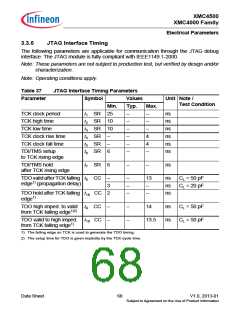
3.3.9
Peripheral Timing
3.3.9.1 Delta-Sigma Demodulator Digital Interface Timing
The data timing is relative to the active clock edge. Depending on the operation mode of
the connected modulator that can be the rising and falling clock edge.
Note: The timing parameters for this interface will be added in a future revision of the
Data Sheet.
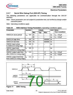
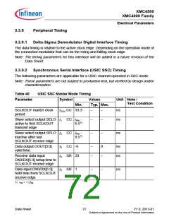
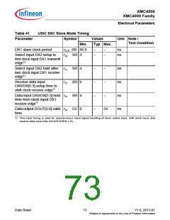
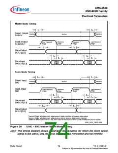
3.3.9.2 Synchronous Serial Interface (USIC SSC) Timing
The following parameters are applicable for a USIC channel operated in SSC mode.
Note: These parameters are not subject to production test, but verified by design and/or
characterization.
Table 40
USIC SSC Master Mode Timing
Symbol Values
Typ. Max.
Parameter
Unit Note /
Test Condition
Min.
CLK CC 33.3
SCLKOUT master clock
period
t
−
−
ns
ns
Slave select output SELO t1 CC tPB
active to first SCLKOUT
-
−
−
6.51)
transmit edge
Slave select output SELO t2 CC tPB
inactive after last
SCLKOUT receive edge
-
−
−
ns
8.51)
t3 CC -6
t4 SR 23
Data output DOUT[3:0]
valid time
−
−
8
ns
ns
Receive data input
−
DX0/DX[5:3] setup time to
SCLKOUT receive edge
Data input DX0/DX[5:3]
hold time from SCLKOUT
receive edge
t5 SR
1
−
−
ns
1)
tPB = 1 / fPB
Data Sheet
72
V1.0, 2013-01
Subject to Agreement on the Use of Product Information

 INFINEON [ Infineon ]