XMC4500
XMC4000 Family
Electrical Parameters
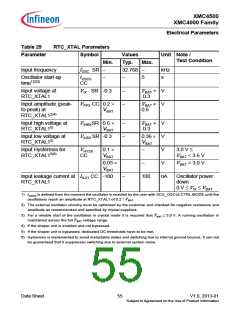
Table 29
RTC_XTAL Parameters
Symbol
Parameter
Values
Typ.
Unit Note /
Test Condition
Min.
fOSC SR −
Max.
Input frequency
32.768 −
kHz
s
Oscillator start-up
time1)2)3)
tOSCS
−
−
−
−
5
CC
Input voltage at
RTC_XTAL1
VIX SR -0.3
VBAT
0.3
+
+
V
V
Input amplitude (peak-
to-peak) at
V
PPX CC 0.2 ×
VBAT
VBAT
0.6
RTC_XTAL12)4)
Input high voltage at
RTC_XTAL15)
V
V
IHBXSR 0.6 ×
−
−
VBAT
0.3
+
V
V
VBAT
Input low voltage at
RTC_XTAL15)
ILBX SR -0.3
0.36 ×
VBAT
Input Hysteresis for
RTC_XTAL15)6)
VHYSX
CC
0.1 ×
VBAT
−
V
3.0 V ≤
V
BAT < 3.6 V
0.03 ×
−
V
V
BAT < 3.0 V
VBAT
Input leakage current at
RTC_XTAL1
I
ILX1 CC -100
−
100
nA
Oscillator power
down
0 V ≤ VIX ≤ VBAT
1)
t
OSCS is defined from the moment the oscillator is enabled by the user with SCU_OSCULCTRL.MODE until the
oscillations reach an amplitude at RTC_XTAL1 of 0.2 * VBAT
.
2) The external oscillator circuitry must be optimized by the customer and checked for negative resistance and
amplitude as recommended and specified by crystal suppliers.
3) For a reliable start of the oscillation in crystal mode it is required that VBAT ≥ 3.0 V. A running oscillation is
maintained across the full VBAT voltage range.
4) If the shaper unit is enabled and not bypassed.
5) If the shaper unit is bypassed, dedicated DC-thresholds have to be met.
6) Hysteresis is implemented to avoid metastable states and switching due to internal ground bounce. It can not
be guaranteed that it suppresses switching due to external system noise.
Data Sheet
55
V1.0, 2013-01
Subject to Agreement on the Use of Product Information

 INFINEON [ Infineon ]