TLE9879QXA40
Application Information
28
Application Information
28.1
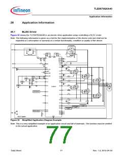
BLDC Driver
Figure 32 shows the TLE9879QXA40 in an electric drive application setup controlling a BLDC motor.
Note:The following information is given as a hint for the implementation of the device only and shall not be
regarded as a description or warranty of a certain functionality, condition or quality of the device.
Rev. Polarity Protection
LPFILT
VBAT
CPFILT
CPFILT
1
1
TRP
CVD DP 2
CVDDP1
CVDDC1
CVDD C2
DRP
EMC Filter
RRP1
RRP2
DVS
TRPG
VDDP VDDC
VS
CP1H
CP1L
CP2H
CCPS1
CVS2
CVS 1
CCPS2
CP2L
VCP
RMON
IGN
LIN
MON
LIN
RVSD
CVCP
CMON
VSD
CVSD
RVDH
VDH
CVD H
CLIN
D
S
GND_LIN
RGATE
G
GH1
SH1
TH1
CPH1
VAREF
RGS
CGS
CVAREF
D
S
GND_REF
G
CEMC P 1
CEMCP 2
CEMCP 3
TH2
CPH2
RGATE
VDD_EXT
P0.3
RGS
CGS
GH2
SH2
CVDD_EXT
CVDD _EXT
2
1
RVDDPU
D
S
TLE4946-2K
Hall
G
RADC
CADC
RGATE
TH3
CPH3
RVDD PU
RGS
CGS
GH3
SH3
TLE4946 -2K
Hall
P1.4
P0.2
RADC
U
V
CADC
RVD DPU
D
S
RGATE
TLE4946 -2K
Hall
G
W
GL1
GL2
GL3
RADC
TL1
TLE9879
CADC
RGS
CGS
D
S
M
RGATE
G
TL2
RGS
CGS
Temp Sensor
P2.2
P1.2
D
S
RGATE
G
TL3
RGS
CGS
SL
ROPAFILT
RGATE
OP2
RShunt
COPAFILT
RGATE
OP1
P1.0
ROPAFILT
Input Protection
Circuit
P2.0
P2.3
P2.4
Input Protection
Circuit
Input Protection
Circuit
TMS
P0.0
Debug Connector
P0.1
P0.4
P2.5
P1.3
GND
RTMS
GND
BLDC System
Figure 32 Simplified Application Diagram Example
Note:This is a very simplified example of an application circuit and bill of materials. The function must be verified
in the actual application.
Data Sheet
77
Rev. 1.0, 2015-04-30

 INFINEON [ Infineon ]