TLE9879QXA40
Current Sense Amplifier
27
Current Sense Amplifier
27.1
Features
Main Features
•
•
•
•
Programmable gain settings: G = 10, 20, 40, 60
Differential input voltage: ± 1.5V / G
Wide common mode input range ± 2 V
Low setting time < 1.4 µs
27.2
Introduction
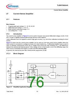
The current sense amplifier in Figure 31 can be used to measure near ground differential voltages via the 10-bit
ADC. Its gain is digitally programmable through internal control registers.
Linear calibration has to be applied to achieve high gain accuracy, e.g. end-of-line calibration including the shunt
resistor.
Figure 31 shows how the current sense amplifier can be used as a low-side current sense amplifier where the
motor current is converted to a voltage by means of a shunt resistor RSH. A differential amplifier input is used in
order to eliminate measurement errors due to voltage drop across the stray resistance RStray and differences
between the external and internal ground. If the voltage at one or both inputs is out of the operating range, the
input circuit is overloaded and requires a certain specified recovery time.
In general, the external low pass filter should provide suppression of EMI.
27.2.1
Block Diagram
VBAT
M
V
5V
AREF
VZERO
Motor
Current
Amplifier
configurable
LP Filter
OP2
OP1
ROPAFILT
Gain: 10, 20, 40, 60
VP
Vzero + (VOP2 -VOP1) * G
10
/
10-bit ADC
RSH
COPAFILT
ROPAFILT
ADC1_OUT_CH1
VN
CSA_CTRL
RStray
Ext. GND
Current_Sense_Amplifier.vsd
Figure 31 Simplified Application Diagram
Data Sheet
76
Rev. 1.0, 2015-04-30

 INFINEON [ Infineon ]